Integrated aeroelasticity measurement system

a measurement system and aeroelasticity technology, applied in the field of aircraft diagnostic measurement systems, can solve the problems of affecting the system under test, mounting sensors or antennas on the surface of the wing, and difficult to obtain desired accuracy without, so as to reduce the drag of the wing

Active Publication Date: 2007-05-03
THE BOEING CO
View PDF4 Cites 50 Cited by
  • Summary
  • Abstract
  • Description
  • Claims
  • Application Information

AI Technical Summary

Benefits of technology

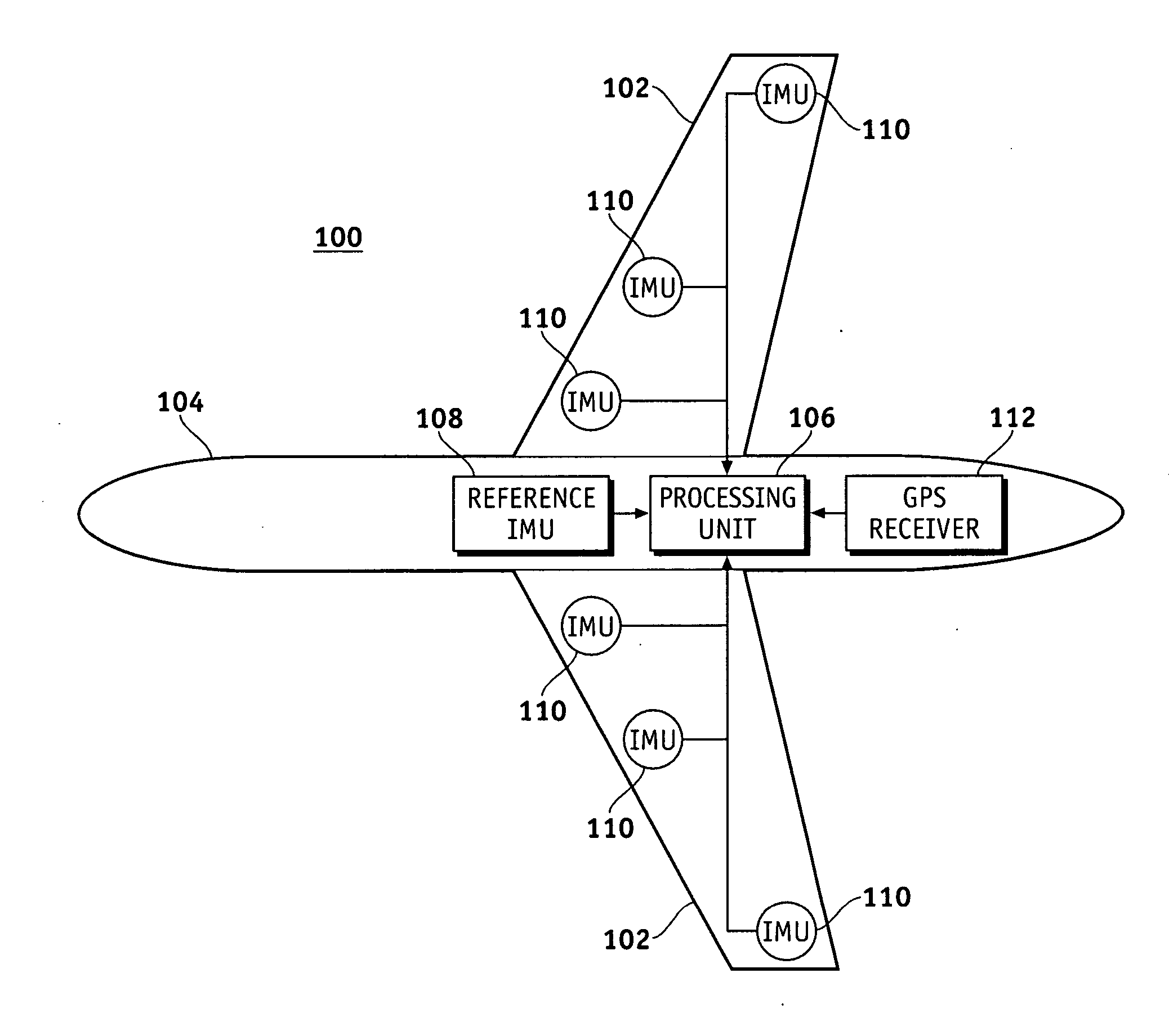
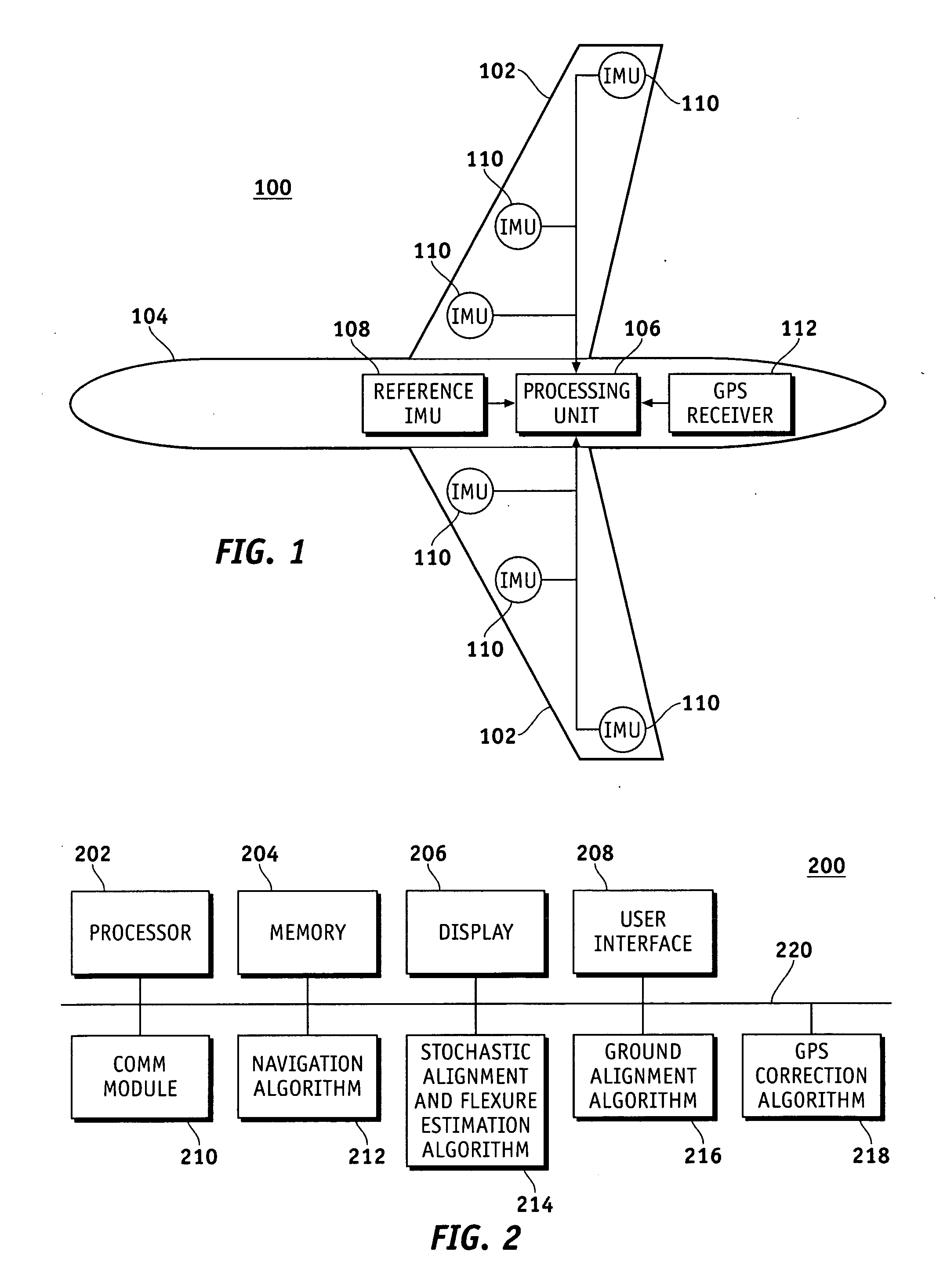
[0006] A system and method is provided for the measurement of elasticity of an airframe, ship, any air, land, or water vehicle, or in general the relative motion of any moving structure. The system and method can be used to validate aerodynamic performance models such as wing models (to reduce wing drag). The, system and method can also be used to validate the need for inertial stabilization of antenna arrays on elastic bodies. An example embodiment of the invention utilizes inertial sensors, a GPS receiver, inertial navigation techniques, and stochastic alignment and flexure estimation techniques integrated into a configurable system controlled by a single processor. The system can also be suitably configured to assist in the accurate mounting of sensors at the measurement points of interest.

Problems solved by technology

For example, mounting a sensor or an antenna on a surface of a wing that would otherwise be void of projections is disruptive to the system under test.
The desired accuracy is difficult to obtain without imposing requirements for occasional maneuvers or other intrusive constraints.
Unfortunately, photogrammetry is intrusive and is subject to variations in accuracy and availability due to weather.
Moreover, a GPS requires an antenna at the desired measurement point, which is intrusive because it may be difficult or impossible to properly mount the GPS antenna in the desired location (for example, in the interior space of the wing).

Method used


Image

  • Integrated aeroelasticity measurement system
  • Integrated aeroelasticity measurement system
  • Integrated aeroelasticity measurement system

Examples


Embodiment Construction

[0013] The following detailed description is merely illustrative in nature and is not intended to limit the invention or the application and uses of the invention. Furthermore, there is no intention to be bound by any expressed or implied theory presented in the preceding technical field, background, brief summary or the following detailed description.

[0014] The invention may be described herein in terms of functional and / or logical block components and various processing steps. It should be appreciated that such block components may be realized by any number of hardware, software, and / or firmware components configured to perform the specified functions. For example, an embodiment of the invention may employ various integrated circuit components, e.g., memory elements, digital signal processing elements, logic elements, look-up tables, or the like, which may carry out a variety of functions under the control of one or more microprocessors or other control devices. In addition, thos...


PUM


Abstract

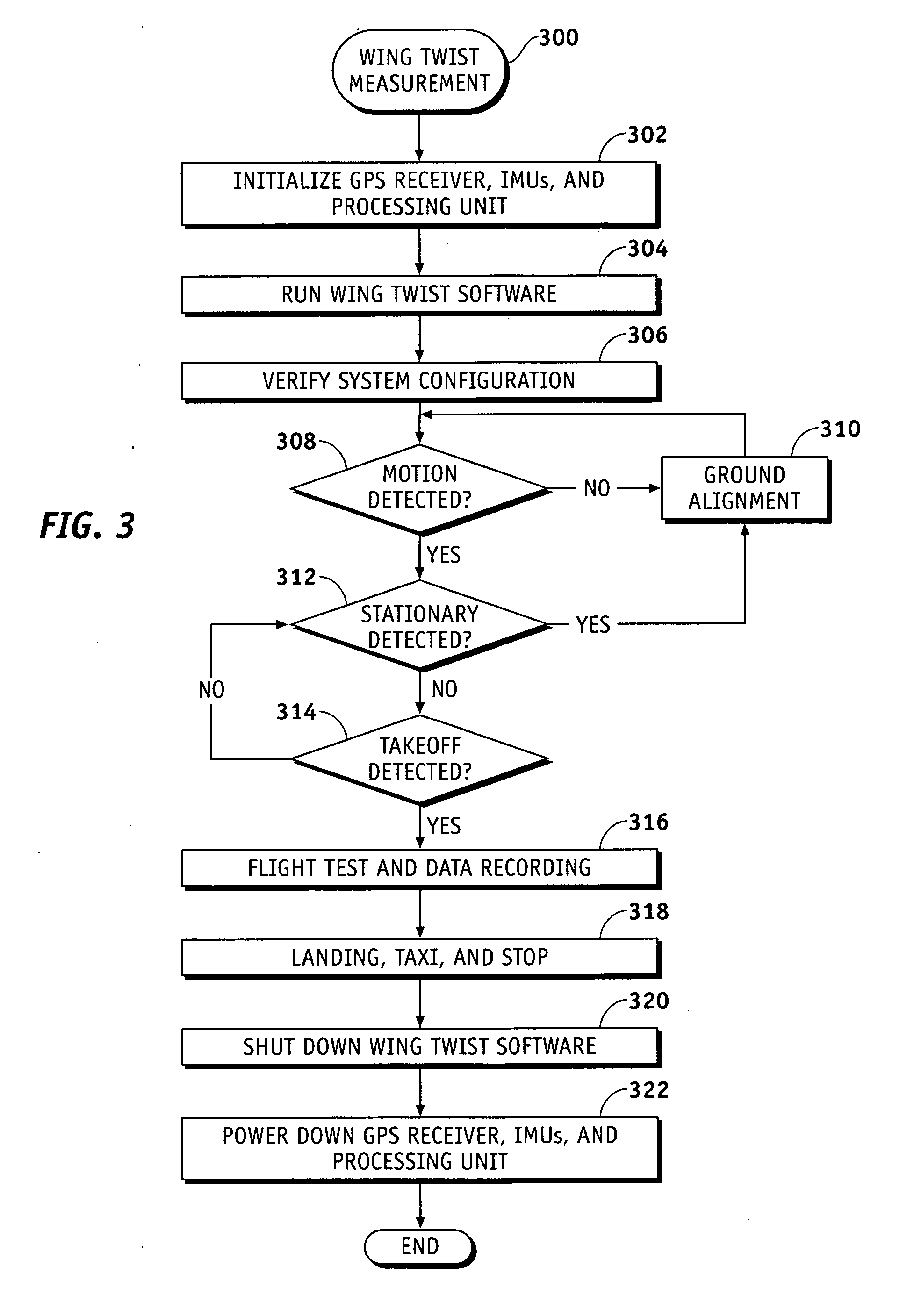
An aircraft aeroelasticity measurement system according to the invention can be used to perform in-flight wing twist measurements of an aircraft or any moving vehicle or structure on which its sensors can be mounted. The system includes a centralized processing unit, a reference navigation unit mounted in the aircraft body, a plurality of measurement navigation units mounted in the aircraft wings, and a global positioning system (“GPS”) receiver that generates GPS data for enhancing the accuracy of the navigation data. The system collects navigation data from the reference navigation unit and the measurement navigation units, generates navigation solutions from the navigation data, and performs a stochastic alignment and flexure estimation procedure to generate a corrected measurement solution that indicates the aeroelasticity of the aircraft. Wing twist and wing deflection information can be derived from the corrected measurement solution.

Description

TECHNICAL FIELD [0001] The present invention relates generally to aircraft diagnostic measurement systems. More particularly, the present invention relates to an in-flight aeroelasticity measurement system suitable for use in measuring wing twist and wing deflection of an aircraft or any moving vehicle or structure to which its sensors can be mounted. BACKGROUND [0002] Aircraft are designed using wing models and computer systems that simulate the aerodynamic properties and characteristics of the wing. For example, a wing model can be used to design a wing for minimum drag for the intended operating conditions. In practice, wing models must be validated with in-flight tests before the aircraft design is accepted for purposes of a deployable build. Such in-flight tests typically include aeroelasticity measurements for the wings and fuselage. [0003] Wing aeroelasticity data usually includes wing twist data and wing deflection data, where wing twist represents axial rotation of the wing...

Claims


Application Information

Patent Timeline
Patent Type & Authority Applications(United States)
IPC IPC(8): G01S5/14G01S19/14G01S19/39
CPCG01M5/0016G01M5/0041G01M5/0066G01S19/14G01S19/39G01S19/393G01S19/396
Inventor HINNANT, HARRIS O. JR.BREKKE, DARIN W.CLINGMAN, DAN J.
Owner THE BOEING CO
Why Eureka
Try Eureka