Protective circuit

a protection circuit and circuit technology, applied in the direction of safety/protection circuits, battery disconnect circuits, electrical devices, etc., can solve the problems of affecting the safety of the battery circuit, the practical protection circuit cannot be allowed to draw more than a few microamperes of current, and the current may be detrimental, so as to achieve the safe operation of the battery circuit

Inactive Publication Date: 2007-05-03
CARETTA INTEGRATED CIRCUITS
View PDF34 Cites 5 Cited by
  • Summary
  • Abstract
  • Description
  • Claims
  • Application Information

AI Technical Summary

Benefits of technology

[0015] In one embodiment, the protective circuit further includes a resistor. The switch connects the bulk terminal of the MOS transistor to the first drain/source terminal through this first resistor, thereby limiting any “rush” current which occurs when the battery circuit switches from discharging to charging, or vice versa, over a very short time period. Consequently, safe operation of the battery circuit is achieved.
[0016] In accordance with another embodiment of the present invention, a protective circuit for a battery includes: (1) an MOS transistor having a first drain/source terminal coupled to one terminal of the battery; (2

Problems solved by technology

However, if not properly used, they can be hazardous.
In some instances, inadvertent large discharge currents or large charging currents have been known to cause fire or even explosion.
Because the protective circuit is always operating, regardless of whether or not a load is connected across the battery, a practical protective circuit cannot be allowed to draw more than a few microamperes of current.
If either of these junctions become forward biased, the parasitic lateral and vertical bipolar transistors may become conducting and the resulting current may be detrimental.
One disadvantage of protective circuit 200 is its requirement that control circuit 74 monitors the current direction during both charging and discharging operatio

Method used


Image

  • Protective circuit
  • Protective circuit
  • Protective circuit

Examples


Embodiment Construction

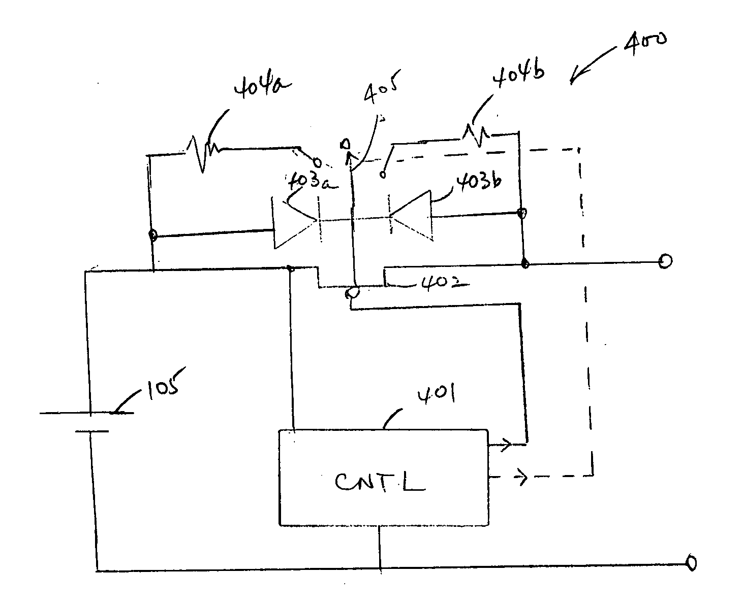
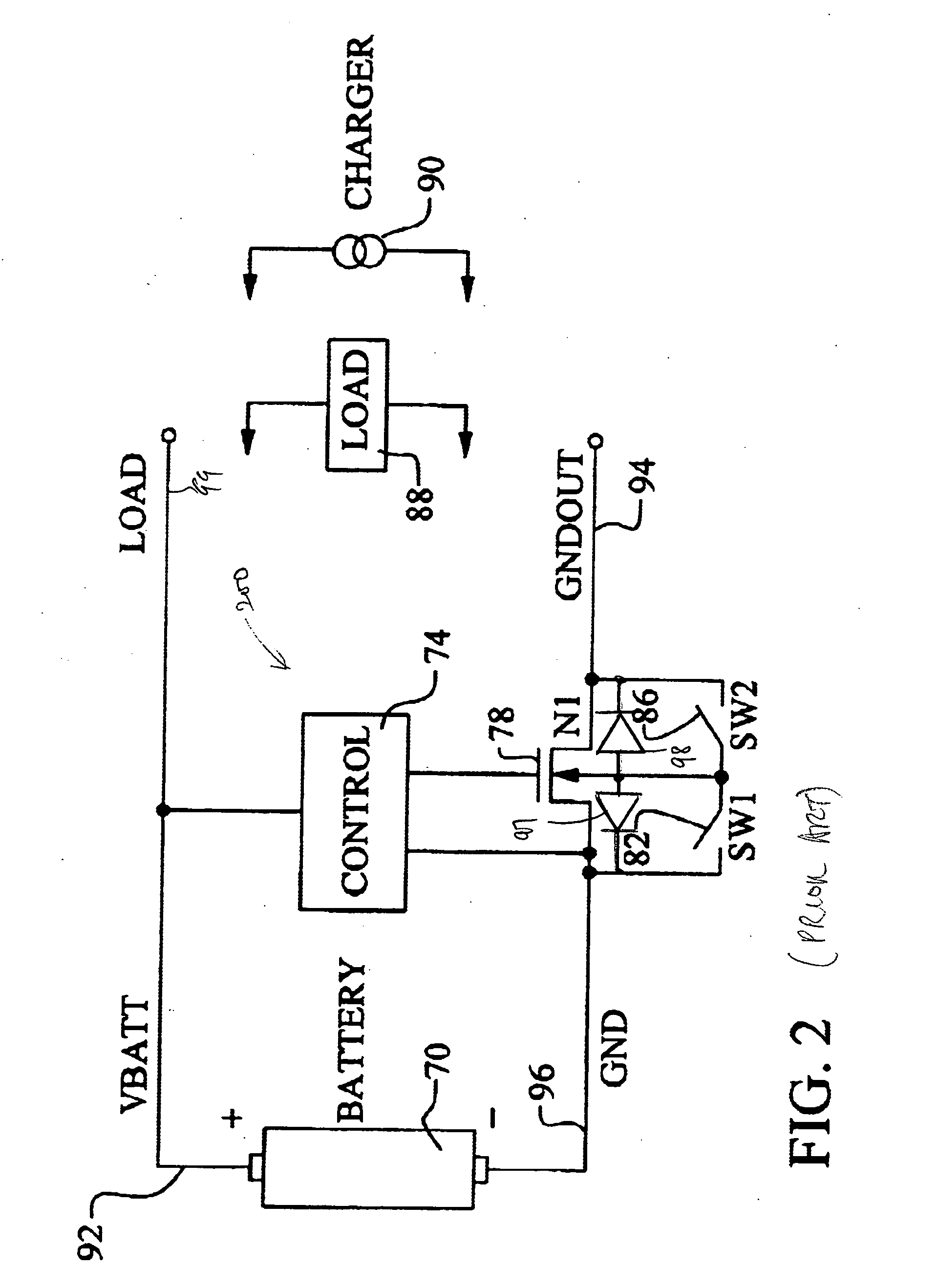
[0024]FIG. 4 shows protective circuit 400, in accordance with one embodiment of the present invention. As shown in FIG. 4, protective circuit 400 includes control circuit 401, MOSFET 402, resistors 404a and 404b, and switch 405. MOSFET 402 includes parasitic diodes 403a and 403b, corresponding respectively to the junctions at its source and drain terminals. Under control of control circuit 401, switch 405 can selectively float the bulk terminal of MOSFET 402, or to connect the bulk terminal of MOSFET 402 to its source terminal or its drain terminal, through resistors 404a and 404b, respectively. During normal operation (i.e., either in a discharging operation or a charging operation), the bulk terminal of MOSFET 402 is allowed to float. Unlike protective circuit 200 of FIG. 2, by floating the bulk terminal of MOSFET 402, protective circuit 400 is not required to detect whether the operation is charging or discharging (hence, there is no need to determine which one of the drain termi...


PUM


Abstract

A protective circuit for a battery includes: (1) an MOS transistor having a first drain/source terminal coupled to one terminal of the battery; (2) a switch selectable to couple the bulk terminal of the MOS transistor to (a) the first drain/source terminal, (b) a second drain/source terminal, or (c) float; and (3) a control circuit which provides control signals for the gate terminal of the MOS transistor and the switch. By allowing the bulk terminal to float during normal operation (i.e., charging or discharging operation), a sensitive, low-power comparator used in the prior art is eliminated, thereby allowing the protective circuit to have a small foot-print. The protective circuit may further include a resistor. The switch connects the bulk terminal of the MOS transistor to the first drain/source terminal through this first resistor, thereby limiting any “rush” current which occurs when the battery circuit switches from discharging to charging, or vice versa, over a very short time period. Consequently, safe operation of the battery circuit is achieved.

Description

BACKGROUND OF THE INVENTION [0001] 1. Field of the Invention [0002] The present invention relates to a protective circuit for a rechargeable battery. In particular, the present invention relates to a low-power, low “rush current” protective circuit suitable for use with a lithium ion battery or lithium ion polymer battery. [0003] 2. Discussion of the Related Art [0004] Lithium ion batteries and lithium polymer batteries are widely use in portable electronic devices because of their high energy density per unit weight or per unit volume. However, if not properly used, they can be hazardous. In some instances, inadvertent large discharge currents or large charging currents have been known to cause fire or even explosion. Therefore, as a safety measure, each lithium ion battery or lithium polymer battery is always provided a protective circuit that limits the current drawn from the battery in the event of an unusual or abnormal operating condition occur. Because the protective circuit ...

Claims


Application Information

Patent Timeline
IPC IPC(8): H02H3/00
CPCH02J7/0031
Inventor WU, BIN
Owner CARETTA INTEGRATED CIRCUITS
Why Eureka
Try Eureka