Single-pass double-sided image transfer process and system

a single-pass, image transfer technology, applied in the direction of coupling/disassembly of coupling parts, coupling device connections, other domestic articles, etc., can solve the problems of significant print and conversion inefficiencies, relative slow and inefficient printing or media card conversion operations, printers taking longer

Active Publication Date: 2007-05-03
ZEBRA TECH CORP
View PDF14 Cites 42 Cited by
  • Summary
  • Abstract
  • Description
  • Claims
  • Application Information

AI Technical Summary

Benefits of technology

[0083] Various embodiments of the present invention address the above problems and achieve other advantages by providing a printing method whereby at least one registration mark 1005 is printed to the IT media 1250 on a first printing pass. In the depicted embodiment, sensors 1015 are provided proximate the IT media 1250 for detecting the location of the at least one registration mark 1005. The sensors 1015 may be optical sensors, photo sensors, infrared sensors, or other types of sensors that may be apparent to one of ordinary skill in the art in view of this disclosure. Sensors 1015 may be disposed adjacent the thermal print head 1235 and the single-pass double-sided image transfer station 1245 as shown. In this regard, the sensors 1015 may detect the position of the printed registration marks 1005 during printing of an image 1010 to the IT media 1250 and during transfer of the image 1010 from the IT media 250 to a media card (not shown). Thus, the precision of the printing and image transfer steps may be substantially enhanced.

Problems solved by technology

However, LEL printers of the type illustrated in FIG. 1 have at least two undesirable design characteristics that result in relatively slow and inefficient printing or media card conversion operations.
As referenced above, LEL printers of the type depicted in FIG. 1 contain paused LEL card encoding and multi-pass printing techniques that cause significant print and conversion inefficiencies.
Further, by shuttling the card back and forth in multiple passes to print to opposed surfaces of the media card the depicted printer takes longer than would be necessary if the printer were able to perform double-sided printing operations in a single-pass.

Method used


Image

  • Single-pass double-sided image transfer process and system
  • Single-pass double-sided image transfer process and system
  • Single-pass double-sided image transfer process and system

Examples


Embodiment Construction

[0034] A number of executions of the present invention now will be described more fully hereinafter with reference to the accompanying drawings, in which some, but not all embodiments of the inventions are shown. Indeed, the present invention may be embodied in many different forms and should not be construed as limited to the embodiments set forth herein; rather, these embodiments are provided so that this disclosure will satisfy applicable legal requirements. Like numbers refer to like elements throughout.

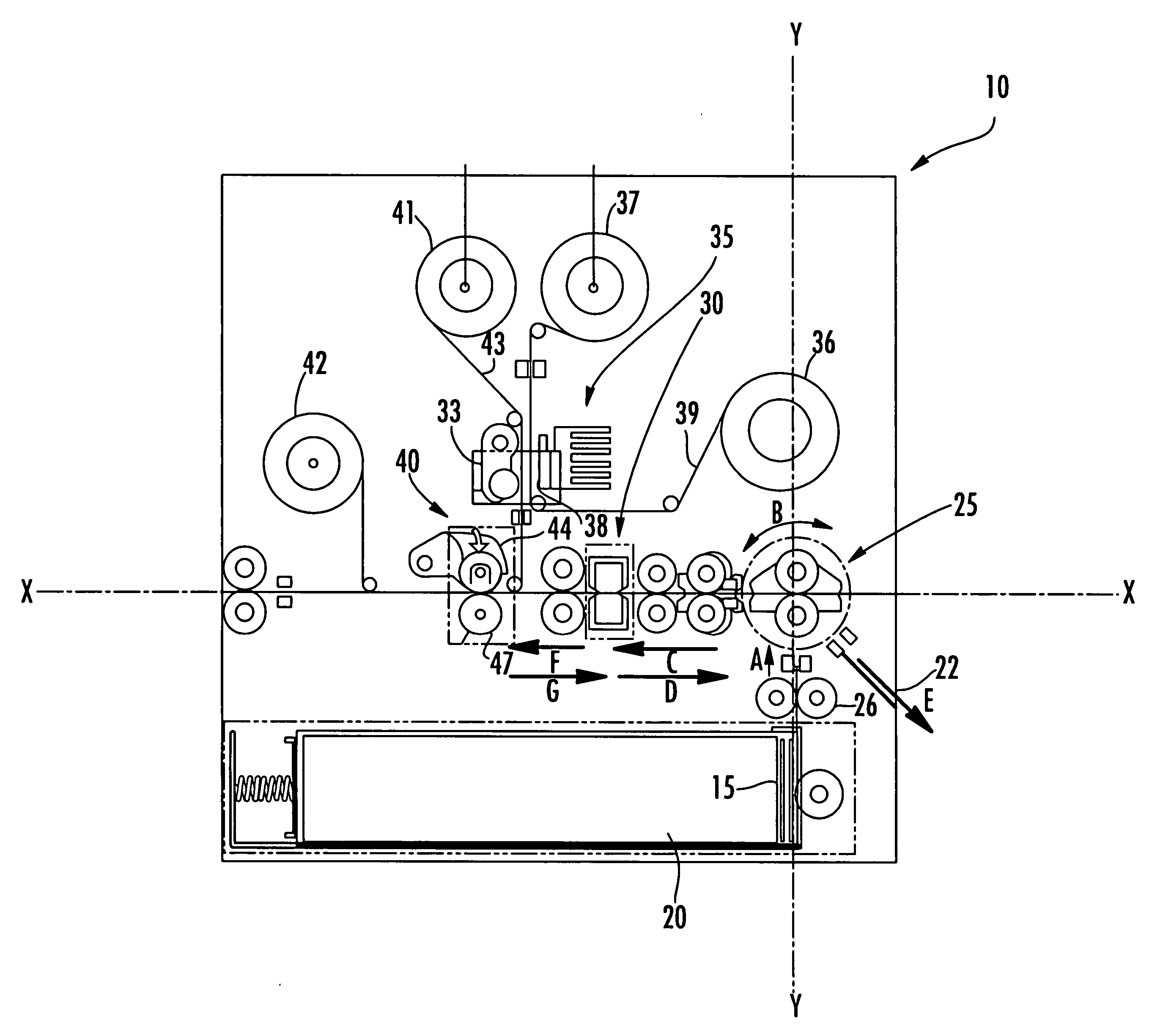
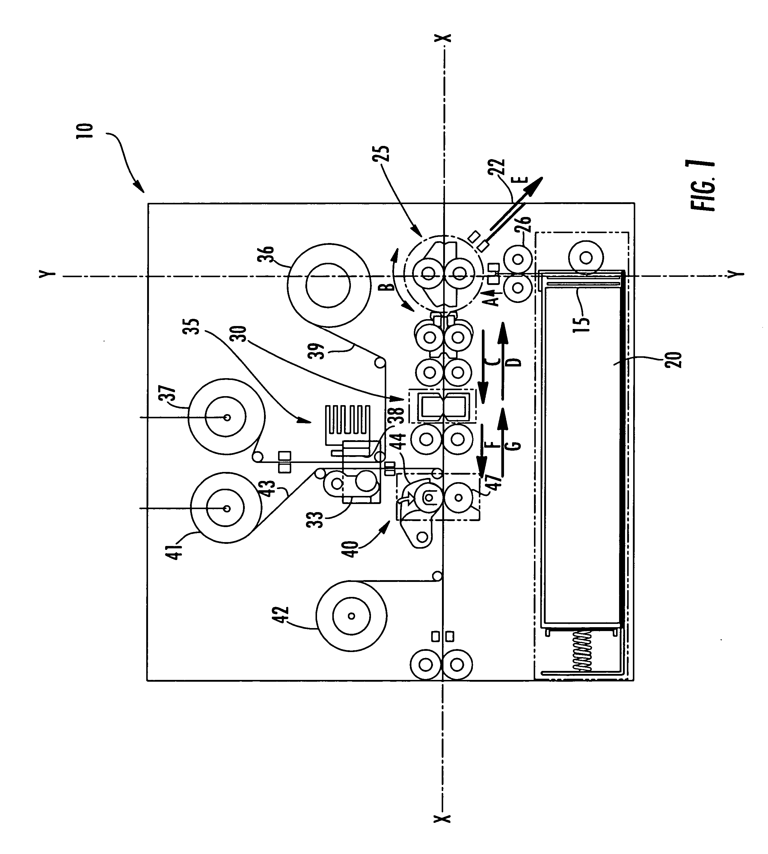
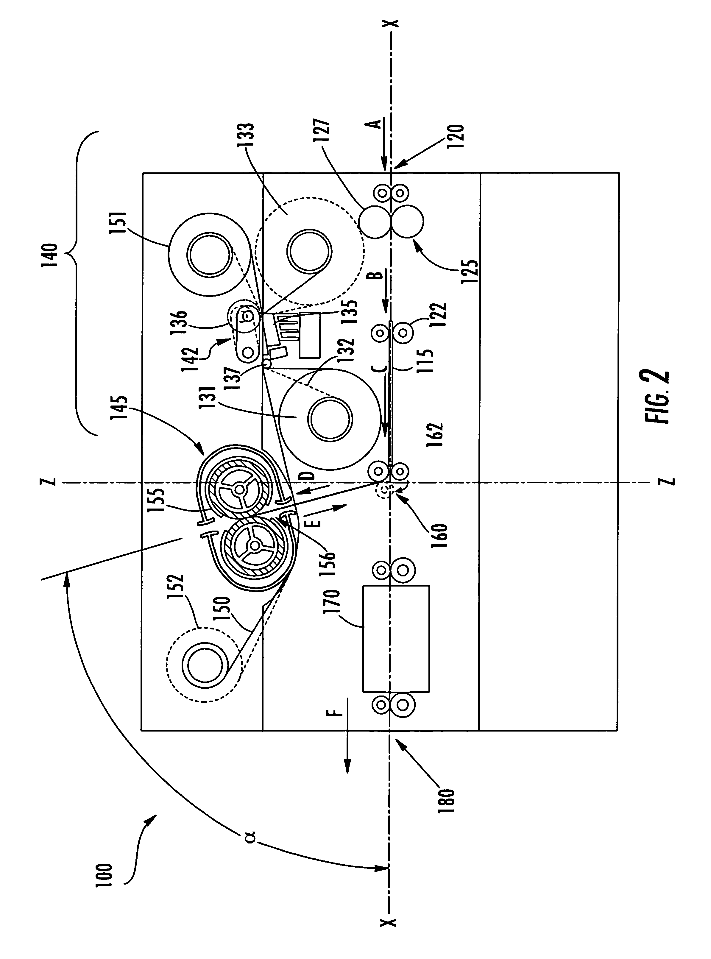
[0035] The present invention addresses the above needs and achieves other advantages by providing a printing assembly incorporating an improved double-sided image transfer station as exemplified in the described embodiments. A media processing device is also disclosed herein that incorporates a cross feed media processing architecture for feeding media to the above double-sided image transfer station or other card conversion stations as described below. Such cross feed architect...


PUM

PropertyMeasurementUnit
processing angleaaaaaaaaaa
anglesaaaaaaaaaa
angleaaaaaaaaaa

Abstract

The present disclosure is directed to a printing assembly incorporating an improved double-sided image transfer station. The present disclosure also describes a product processing apparatus including a cross feed processing architecture. The single-pass double-sided image transfer station and cross feed processing architectures described herein provide numerous advantages over prior art product processing devices. In particular, the single-pass double-sided image transfer station provides for reduced print times, less shuttling of the product during printing, and a less complex, therefore, more reliable printing operation overall. The cross feed architecture provides an efficient processing path for the product through the device and facilitates processing modularization.

Description

CROSS-REFERENCE TO RELATED APPLICATIONS [0001] The present application claims priority to U.S. Provisional Application. No. 60 / 673,203 filed Apr. 20, 2005; the contents of which are incorporated herein in their entirety.BACKGROUND OF THE INVENTION [0002] 1. Field of the Invention [0003] The present invention is directed to a method, device, and system for transferring images to both sides of media cards or other products, and more particularly to a single-pass double-sided image transfer system that may find beneficial use in printing cards and other media. [0004] 2. Description of the Related Art [0005]FIG. 1 depicts a long edge leading double-sided printer in accordance with the known prior art. The printer is structured to print rectangular media cards such as PVC media cards that are commonly known in the art. The phrase “long edge leading” refers to the primary orientation taken by media cards as they are manipulated through the printer during printing operations. In a long edg...

Claims


Application Information

Patent Timeline
Patent Type & Authority Applications(United States)
IPC IPC(8): H01R13/62
CPCB32B37/025B32B37/142B32B37/185B32B38/18B32B2425/00B32B2429/00B32B2519/02B41J2/0057B41J2/325B41J3/60B41J13/12B32B38/1816
Inventor HELMA, THOMAS RICHARDJONES, TERRENCE K.MAYNARD, RAYMOND EUGENESADECK, RICHARD MICHAEL
Owner ZEBRA TECH CORP
Why Eureka
Try Eureka