
Polyetrafluoroethylene micropowder compositions

Inactive Publication Date: 2007-05-03
AGC CHEM AMERICAS INC
View PDF10 Cites 13 Cited by
  • Summary
  • Abstract
  • Description
  • Claims
  • Application Information

AI Technical Summary

Benefits of technology

[0012] Accordingly, one object of the invention is to provide PTFE-containing compositions that address the problems noted above. The object of the invention is achieved in one embodiment which includes fluoroelastomer compositions containing one or more fluoroelastomers or one or more fluoroelastomers comprising copolymerized units of alternating tetrafluoroethylene and propylene units, and thereby provide improved molding or extrusion performance when mixed, milled, or extruded in the presence of a PTFE micropowder composition. In a further embodiment the fluoroelastomer compositions may contain a micropowder PTFE composition containing a granular PTFE micropowder having a number average molecular weight of from 105-106, a fine powder PTFE micropowder having a number average molecular weight of from 104-105, and a fine powder molding resin having a number average molecular weight of from 106-107.

Problems solved by technology

An undesired side effect caused by the addition of high molecular weight PTFE to an elastomeric composition may include the formation of surface blemishes during extrusion and / or molding.
In addition, unacceptably high hardness and / or modulus may result in cured vulcanizates of PTFE-containing fluoroelastomer or elastomer compositions.
Thus, cosmetic defects caused by the PTFE fibril network have limited the use of such compositions to applications where surface appearance is not critical or important.
However, lower molecular weight PTFE or fluoroolefin copolymers may exhibit less fibrillation and consequently the resulting compositions may provide reduced tensile strength and less than satisfactory tear properties in comparison to compositions containing higher molecular weight PTFEs.
Conventionally it has been thought that lower molecular weight PTFEs are not capable of improving the physical properties of fluoroelastomers or other elastomers because lower molecular weight PTFE materials are not capable of providing sufficient fibrillation and hence may not form extensive reinforcing networks.
This ribbon and / or fibrous form network may not provide the desirable reinforcing properties of fibrillated high molecular weight PTFEs.

Method used

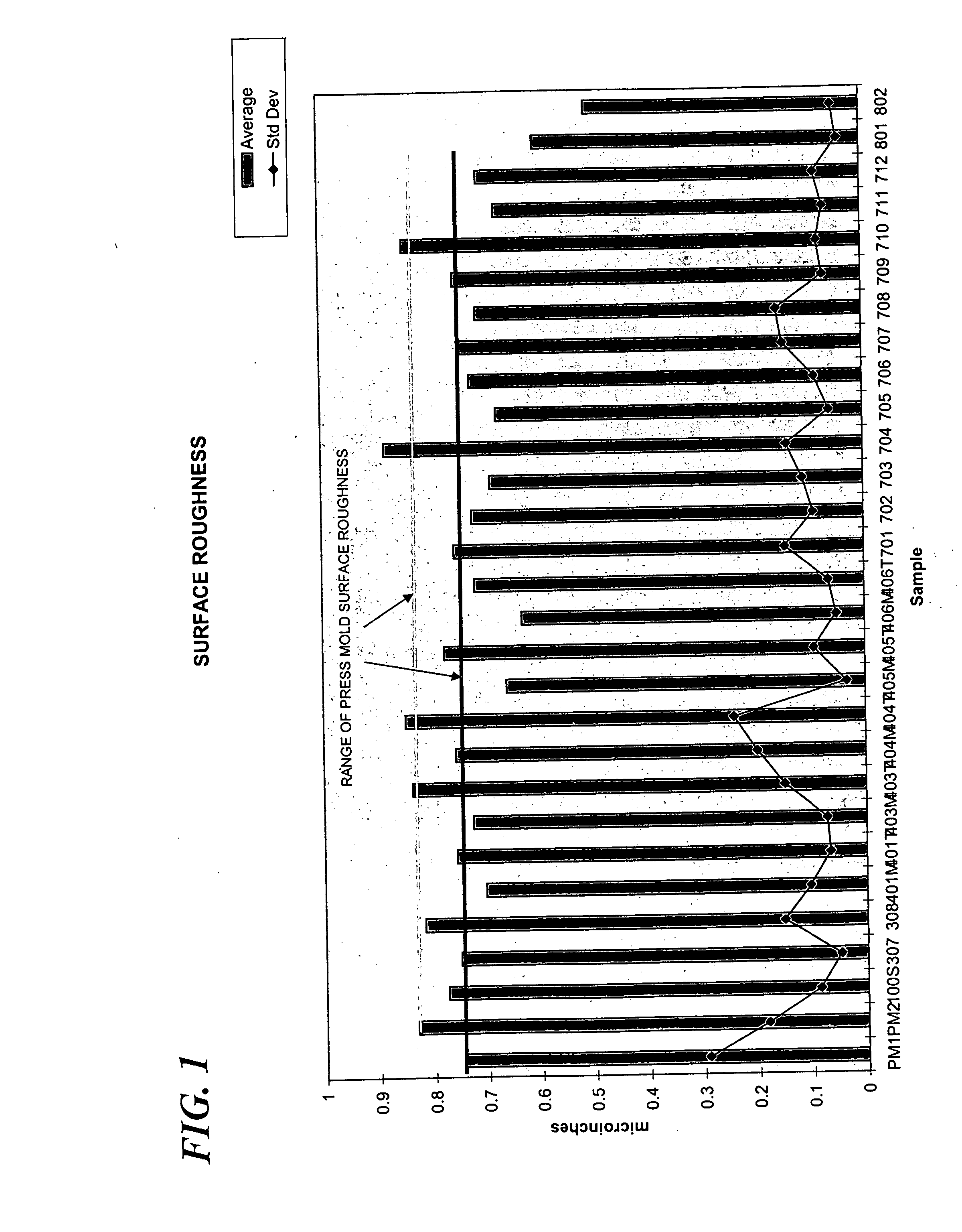
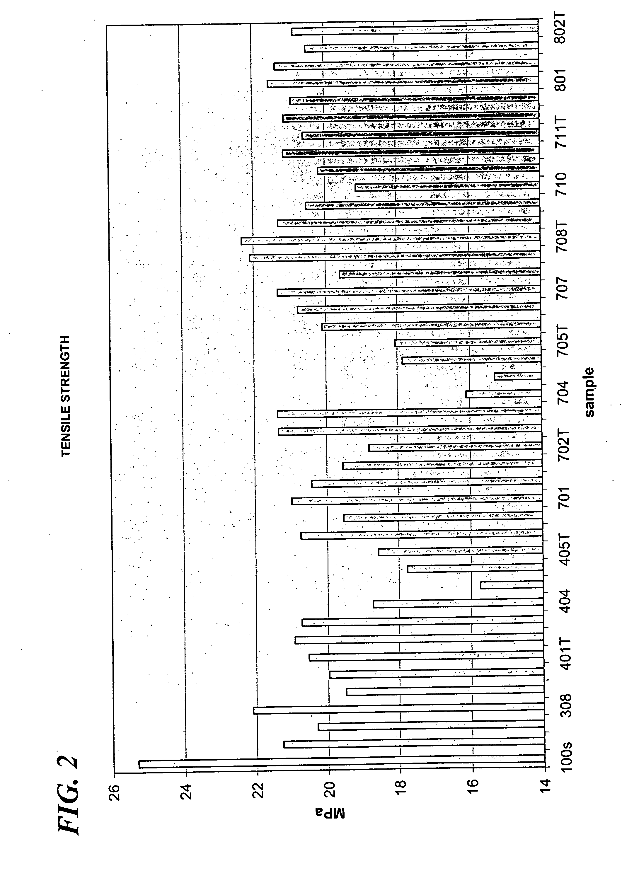
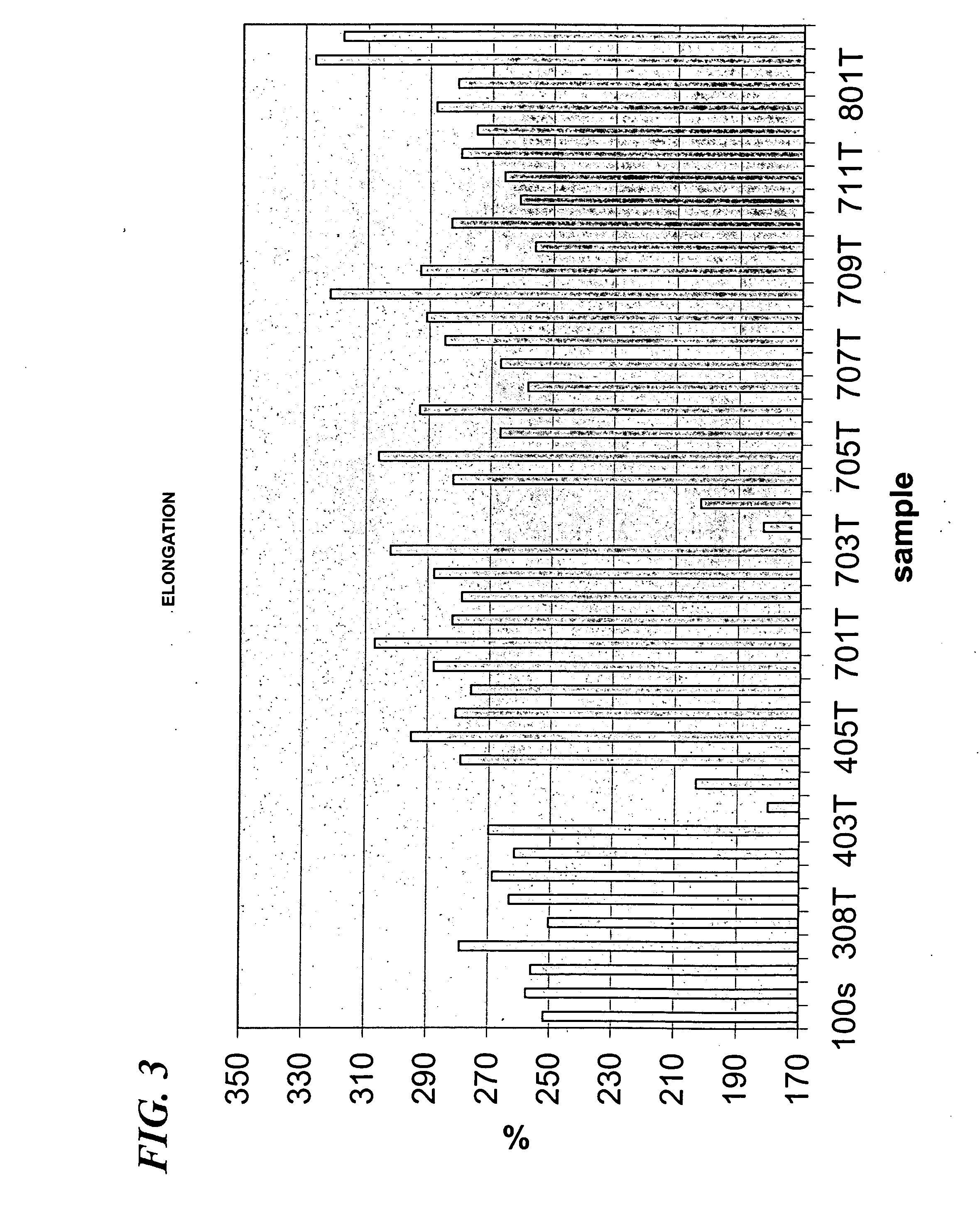

Image

  • Polyetrafluoroethylene micropowder compositions
  • Polyetrafluoroethylene micropowder compositions
  • Polyetrafluoroethylene micropowder compositions

Examples


examples

[0076] Molecular Weight Determination:

[0077] Using the AGC method, molecular weight is calculated using the formula [1.86667×10¹¹{AHc(cal / gm)−5.16}] where ΔHc is the heat of crystallization measured by differential scanning calorimetry. Typical conditions for a Molecular Weight Determination include using a calibrated DSC (Differential Scanning Calorimeter) with a good baseline; Measure out sample of 10 mg + / −0.25 mg. Heat the polymer (PTFE) up to 350° C. at 10° C. / minute. Hold at 350° C. until DSC equilibrates (approx. 1 minute). Cool sample to 250° C. at 10° C. / minute. Heating curve temperature capture is 265 to 350° C. range. Cooling curve temperature capture is 260 to 330° C. range. Then using the AGC calculation to determine number average molecular weight. The number average molecular weights for the various PTFE materials used in the following examples are provided in Table 1 below.

TABLE 1Molecular weights of various PTFE gradesHcCalculatedTemperatureΔ HcNumber AverageDesc...


PUM

PropertyMeasurementUnit
Temperatureaaaaaaaaaa
Volumeaaaaaaaaaa

Abstract

A micropowder composition containing a granular PTFE micropowder, a fine powder PTFE micropowder, and a fine powder molding resin provides mixtures with fluoroelastomers containing copolymerized and alternating units of tetrafluoroethylene and propylene that provide molded articles having improved surface smoothness characteristics and tear resistance on molding. Processes for mixing additives with fluoroelastomers by adding or mixing the fluoroelastomer with the additives in the presence of micropowder PTFE compositions.

Description

BACKGROUND OF THE INVENTION [0001] 1. Field of the Invention [0002] The invention relates to polytetrafluoroethylene (PTFE) micropowder compositions containing mixtures of PTFE micropowders, and fluoroelastomer compositions that contain the micropowder compositions. The invention further relates to mixing, milling, molding or extrusion processes that include mixing, milling, molding or extruding tetrafluoroethylene / propylene elastomers in the presence of the PTFE micropowder compositions and may include adding one or more additives to a fluoroelastomer composition as a mixture with the PTFE micropowder compositions. [0003] 2. Description of the Related Art [0004] Polytetrafluoroethylene (PTFE) micropowders may be used as additives in fluoroelastomer compositions to provide improved abrasion resistance, reduced coefficient of friction, and improved surface characteristics in molded and / or extruded parts. High molecular weight PTFE has been used in elastomeric compositions as a reinfo...

Claims


Application Information

Patent Timeline
IPC IPC(8): C08L27/12
CPCC08L27/18C08L2205/03C08L2666/04
Inventor LAVANGA, DAVID J.DELUCCA, RICHARD
Owner AGC CHEM AMERICAS INC
Learn More