Cold stocker
a stocker and cold technology, applied in the field of cold stockers, can solve the problems of large amount of cooling air that needs to be blown to the radiator, large amount of power consumed by the fan, and large noise, so as to reduce the thermal load of the heat dissipation system, reduce power consumption, and improve the heat dissipation efficiency of the whole heat dissipation system
- Summary
- Abstract
- Description
- Claims
- Application Information
AI Technical Summary
Benefits of technology
Problems solved by technology
Method used
Image

Examples
first embodiment
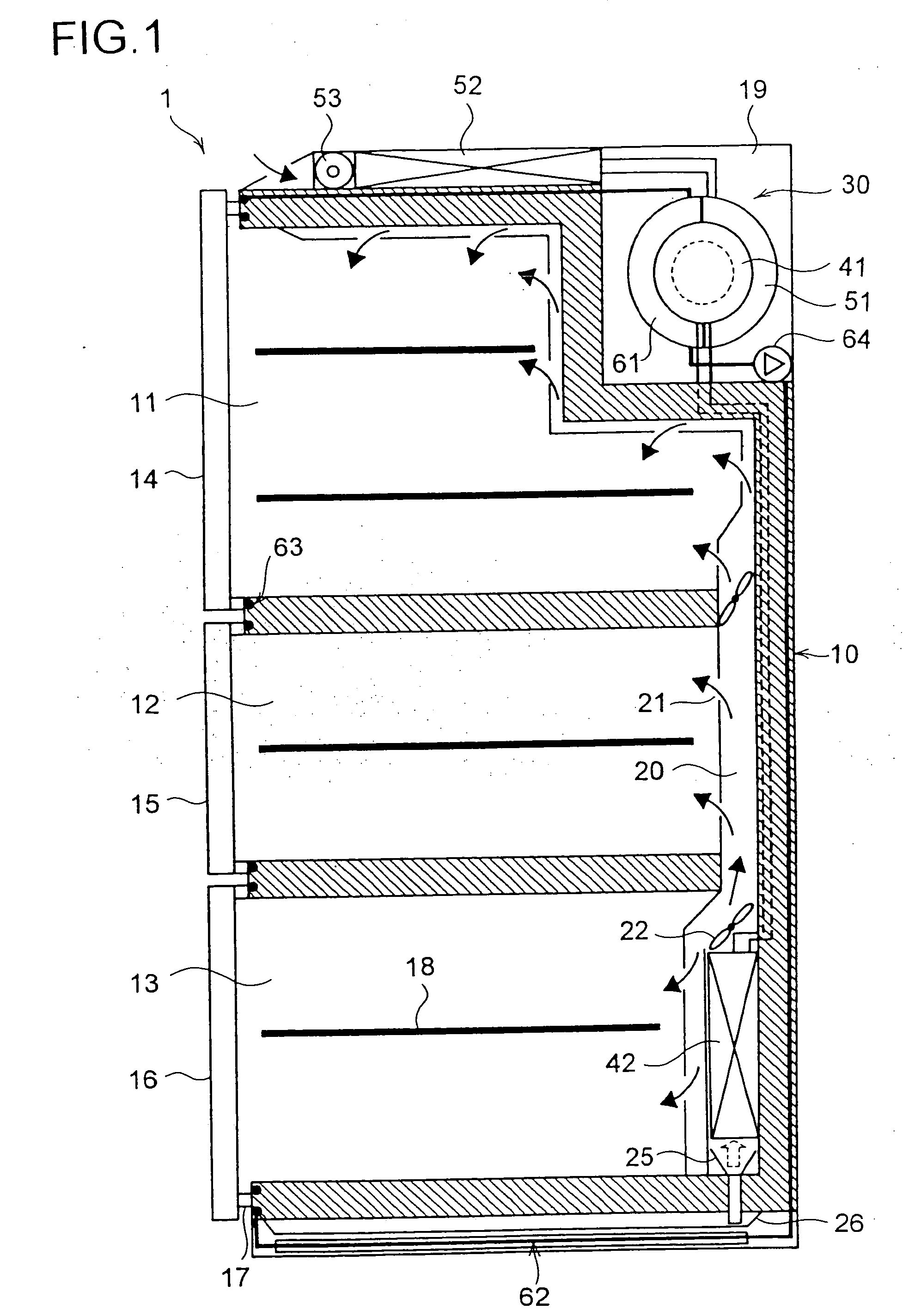
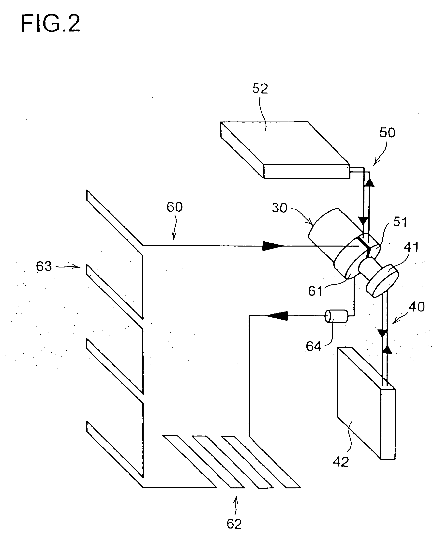
[0070] From a top, to a rear, and further to a bottom of the housing 10, a cooling system and a heat dissipation system are arranged having a Stirling refrigerating engine as their main component. FIG. 1 (sectional view) and FIG. 2 (piping arrangement diagram) show a first embodiment thereof.
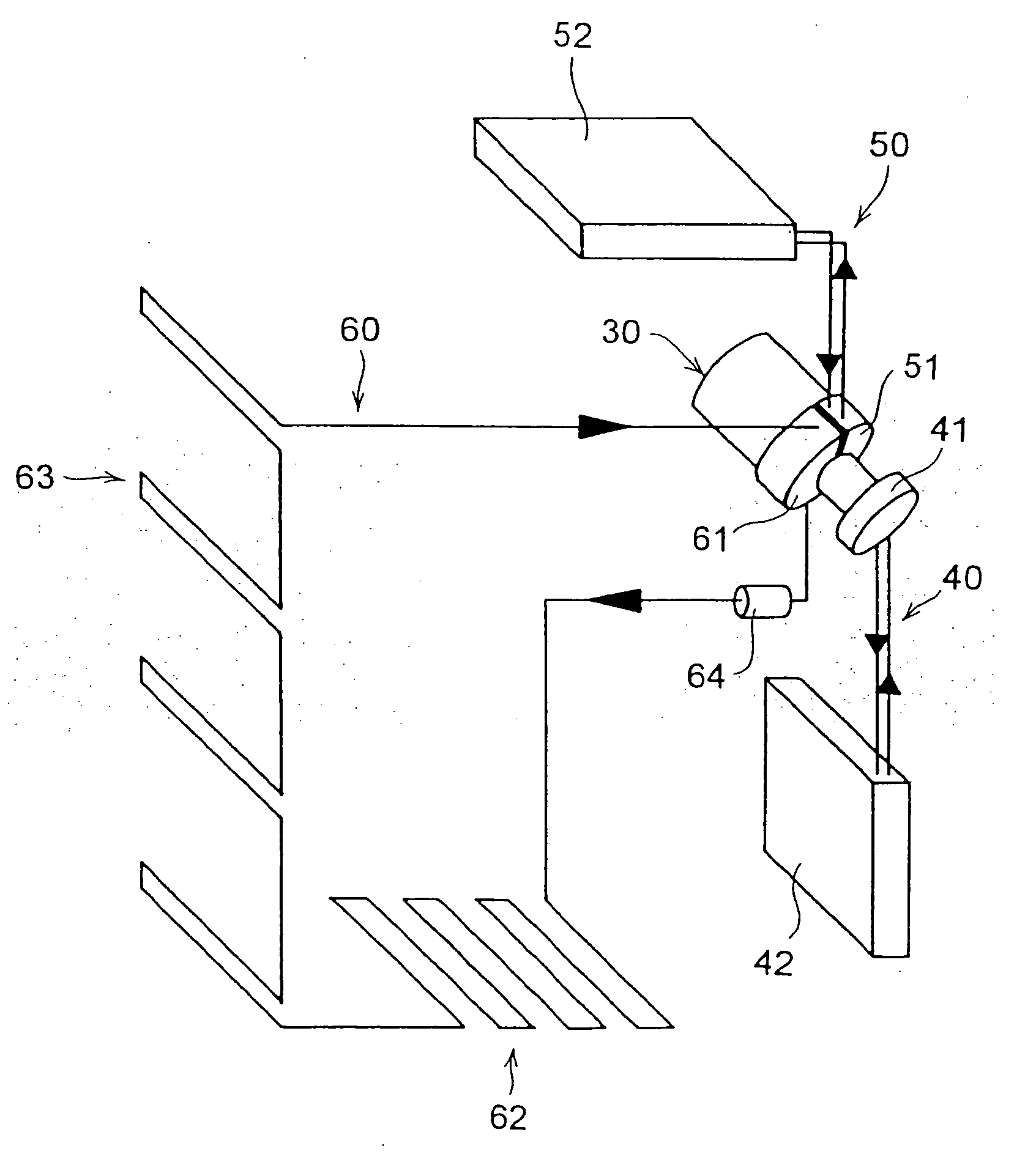
[0071] In a corner between the top and the rear of the housing 10, a mounting space 19 is formed, in which a Stirling refrigerating engine 30 is mounted. Part of the Stirling refrigerating engine 30 is a cold section, to which a cold-side heat exchanger 41 is fitted. In the back of the cooling compartment 13, a compartment-cooling heat exchanger 42 is mounted. The cold-side heat exchanger 41 and the compartment-cooling heat exchanger 42 are connected to each other via a refrigerant pipe so as to form a cold-side refrigerant circulation circuit 40 (see FIG. 2). The cold-side refrigerant circulation circuit 40 is charged with a natural refrigerant such as CO2. Inside the cold-side heat exchanger 4...
second embodiment
[0106] the cold stocker of the present invention is illustrated in FIG. 3. Here, the heat exchange portion 62 for promoting evaporation in drainage and the heat exchange portion 63 for preventing dew condensation on the cold stocker wall are connected in parallel with each other, and this parallel connection configuration is connected in series with the second warm-side heat exchanger 61 and the circulation pump 64. In this embodiment, too, the circulation pump 64 is arranged at the most upstream part of the second warm-side refrigerant circulation circuit 60. Inside the parallel connection configuration, a valve 65 is connected to the heat exchange portion 62 at the upstream side thereof, and a valve 66 is connected in series with the heat exchange portion 63 at the upstream side thereof.
[0107] With the above structure, the flow resistance of the refrigerant at the heat exchange portions 62 and 63 is approximately half that in the first embodiment, and thus the power consumption of...
third embodiment
[0112] In the third embodiment, the warm-side heat exchanger 71 built as one block is fitted to the warm section of the Stirling refrigerant engine 30. As in the first warm-side heat exchanger 51 and the second warm-side heat exchanger 61, a great number of fins are provided in the warm-side heat exchanger 71 so as to achieve efficient heat exchange with the refrigerant. To the warm-side heat exchanger 71, there are connected the circulation pump 64, the heat exchange portion 62 for promoting evaporation in drainage, the heat exchange portion 63 for preventing dew condensation on the cold stocker wall, and heat exchanger 52 for dissipating heat in this order from the upstream of the flow of the refrigerant to form a serial circuit so as to form a warm-side refrigerant circulation circuit 70.
[0113] When the Stirling refrigerating engine 30 is driven, the warm-side heat exchanger 71 is heated. When the warm-side heat exchanger 71 is heated, the refrigerant starts evaporating so as to ...
PUM
 Abstract
Description
Claims
Application Information
 - R&D
- Intellectual Property
- Life Sciences
- Materials
- Tech Scout
- Unparalleled Data Quality
- Higher Quality Content
- 60% Fewer Hallucinations
Browse by: Latest US Patents, China's latest patents, Technical Efficacy Thesaurus, Application Domain, Technology Topic, Popular Technical Reports.
© 2025 PatSnap. All rights reserved.Legal|Privacy policy|Modern Slavery Act Transparency Statement|Sitemap|About US| Contact US: help@patsnap.com