Multi-stage water purification device

a water purification device and multi-stage technology, applied in sedimentation settling tanks, sedimentation regulating devices, feed/discharge settling tanks, etc., can solve the problems of large user force, inability to access the purified water, and natural contamination of drinking water sources, so as to reduce the volume

Inactive Publication Date: 2007-05-10
MARMON WATER SINGAPORE
View PDF19 Cites 44 Cited by
  • Summary
  • Abstract
  • Description
  • Claims
  • Application Information

AI Technical Summary

Benefits of technology

[0012] Water is introduced into the untreated water compartment. The treated water compartment is deformed (squeezed) to reduce its volume therein. As the compartment is let go, it returns its initial volume which provides a negative pressure to draw the water through the filter into the treated water compartment. The untreated water compartment can include an air inlet in communication with the environs. The air inlet is configured as a unidirectional valve to permit air flow into the untreated water compartment and to prevent flow out of the untreated water compartment.

Problems solved by technology

Filtering and purifying water to make it suitable for drinking have been an on-going challenge throughout the world, particularly in developing countries.
Sources of drinking water can be naturally contaminated, as by biological impurities, and / or contaminated by chemical and other non-naturally occurring sources.
However, access to water thus purified is not always available.
One principle drawback to these purifiers is that the user must exert a large force (as by sucking action) to draw the water through the purifier.
Although this system functions well, it has a major limitation in that the bottle must be kept in a vertical position while in use.
This may be contrary to normal use, in which a user would typically tilt the bottle to obtain a drink.
However, flow through the filter relies on gravity and is thus quite slow.

Method used


Image

  • Multi-stage water purification device
  • Multi-stage water purification device
  • Multi-stage water purification device

Examples


Embodiment Construction

[0023] While the present invention is susceptible of embodiment in various forms, there is shown in the drawings and will hereinafter be described a presently preferred embodiment with the understanding that the present disclosure is to be considered an exemplification of the invention and is not intended to limit the invention to the specific embodiment illustrated.

[0024] It should be further understood that the title of this section of this specification, namely, “Detailed Description Of The Invention”, relates to a requirement of the United States Patent Office, and does not imply, nor should be inferred to limit the subject matter disclosed herein.

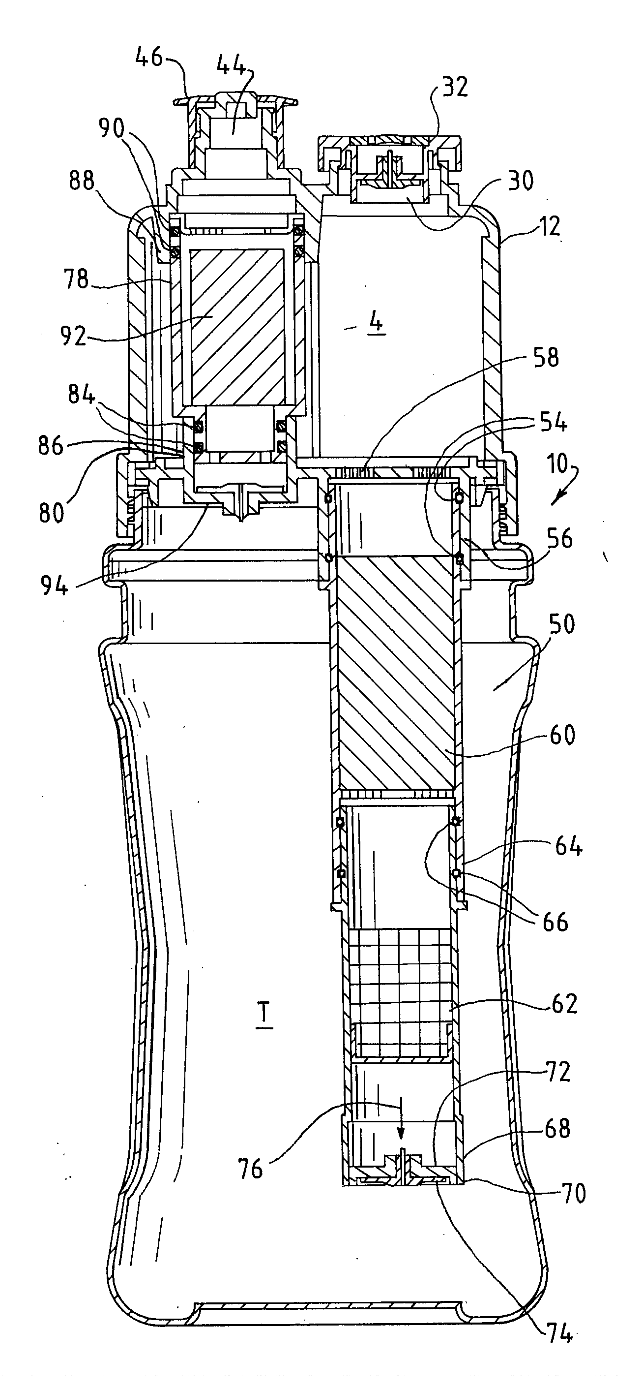
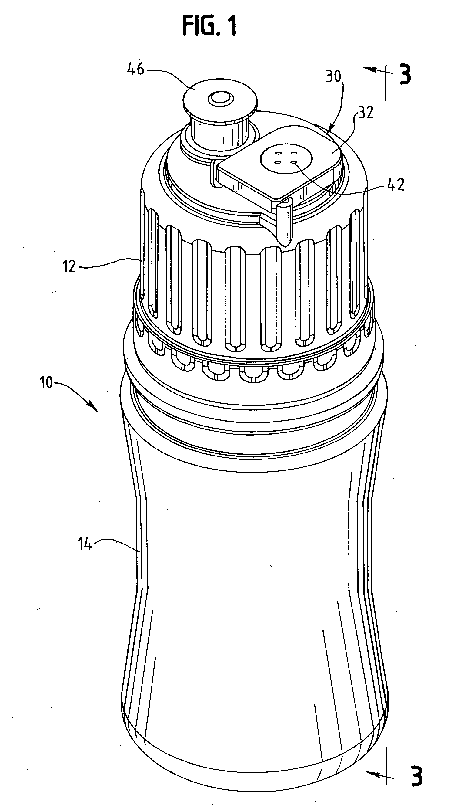
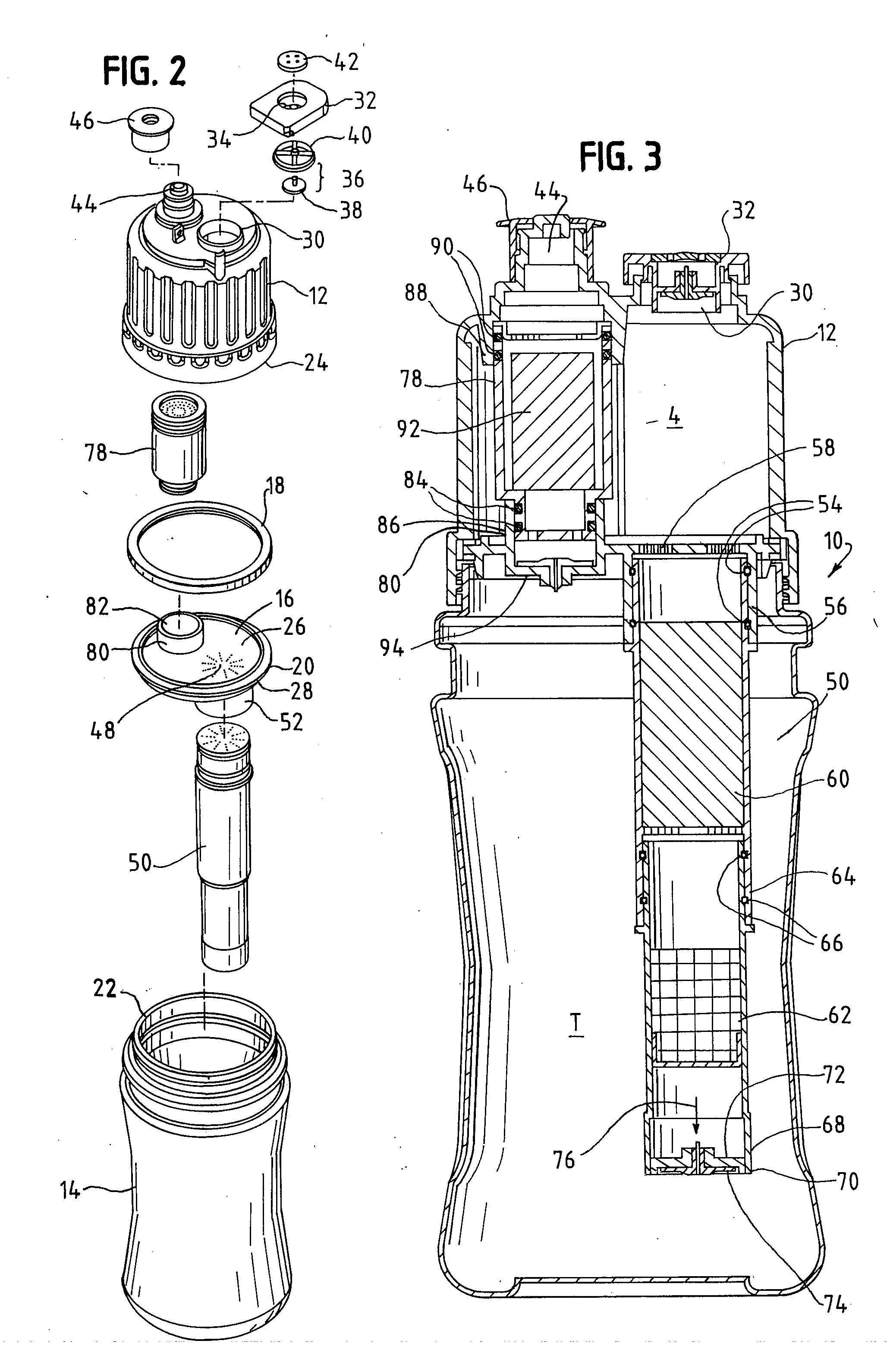
[0025] Referring now to the figures, and in particular to FIG. 1 there is shown a multi-stage water purification device 10 in accordance with the principles of the present invention. The device 10 includes an upper compartment 12 and a lower compartment 14 separated from one another by a center or separator plate 16. As is readily ap...


PUM

PropertyMeasurementUnit
volumeaaaaaaaaaa
pressureaaaaaaaaaa
resilientaaaaaaaaaa

Abstract

A multi-stage water purification device includes an untreated water compartment having an untreated water inlet and a treated water compartment formed from a resilient material. The compartments are segregated from one another. An outlet is in flow communication with the treated water compartment. A first unidirectional valve is disposed between the treated water compartment and the outlet and is configure to permit flow out of the treated water compartment only. A filter is disposed between the untreated water compartment and the treated water compartment. The untreated water flows through the filter to produce treated water. A second unidirectional flow valve is positioned at the discharge of the filter and is configured to permit flow out of the filter and into the treated water compartment only. Water is introduced into the untreated water compartment and the treated water compartment is deformed to reduce the volume therein. As the treated water compartment returns to its initial volume it provides a negative pressure to draw the water through the filter into the treated water compartment.

Description

BACKGROUND OF THE INVENTION [0001] The present invention is directed to a water filtration system. More particularly, the present invention is directed to a portable water filtration system in which unfiltered and filtered water are stored in chambers separated from one another and in which water flows through a filter having a unidirectional valve that permits flow only from the unfiltered chamber to the filtered chamber. [0002] Filtering and purifying water to make it suitable for drinking have been an on-going challenge throughout the world, particularly in developing countries. Sources of drinking water can be naturally contaminated, as by biological impurities, and / or contaminated by chemical and other non-naturally occurring sources. [0003] Large scale, e.g., land-based purification systems have been developed to address the problem of contaminated water supply. However, access to water thus purified is not always available. To meet the needs of traveling public, several porta...

Claims


Application Information

Patent Timeline
Patent Type & Authority Applications(United States)
IPC IPC(8): B01D21/30
CPCB01D21/0012B01D21/0024B01D21/02
Inventor BOMMI, GOVINDBOMMI, KRISHNA MURTHY
Owner MARMON WATER SINGAPORE
Why Eureka
Try Eureka