Antitheft system

a technology of anti-theft system and detection angle, which is applied in the direction of anti-theft devices, galvano-magnetic hall-effect devices, instruments, etc., can solve the problems of temperature drift of signal value that cannot be compensated in terms of preventing false detection, and achieve the improvement of detection angle accuracy, accuracy of detected temperature, and accuracy of detected angl

Inactive Publication Date: 2007-05-10
DENSO CORP
View PDF11 Cites 10 Cited by
  • Summary
  • Abstract
  • Description
  • Claims
  • Application Information

AI Technical Summary

Benefits of technology

[0013] Furthermore, the angle sensor and the temperature sensor are disposed on the same substrate, or in the same case. In this manner, accuracy of the detected temperature is improved, thereby improving the accuracy of the detected angle.
[0014] Furthermore, the angle sensor and the temperature sensor are preferably isolated from a power supply circuit. In this manner, the angle sensor and the temperature sensor are prevented from the influence of heat from the power supply circuit, thereby enabling the improvement of the accuracy of the detected angle.
[0015] Furthermore, the temperature may be detected by various components that is coupled with the antitheft system. For example, an elect

Problems solved by technology

However, even when the initial value of the angle calculation is periodically updated, a sudden change of the temperature in a l

Method used


Image

  • Antitheft system
  • Antitheft system
  • Antitheft system

Examples


first embodiment

[0023] (First Embodiment)

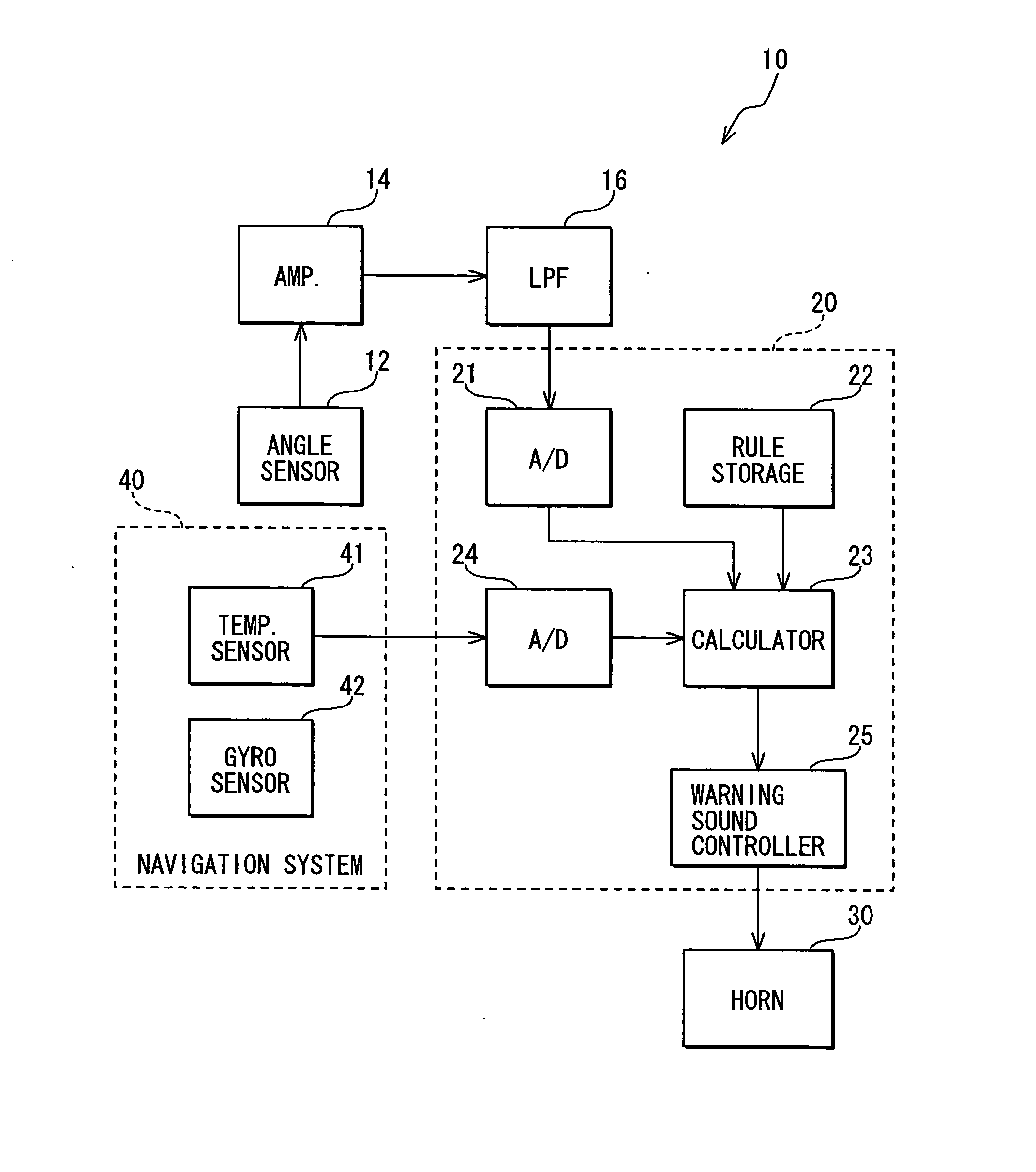
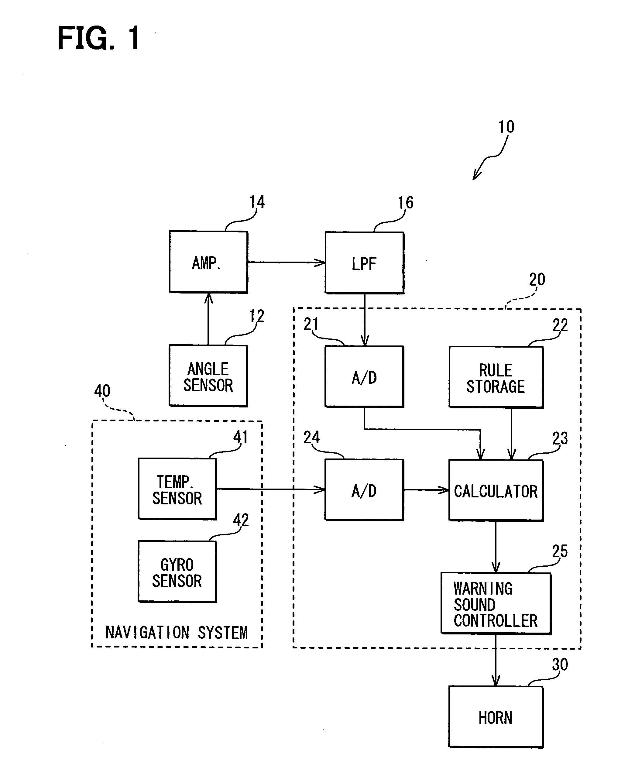
[0024]FIG. 1 shows a block diagram of an antitheft system 10 in a first embodiment of the present disclosure.

[0025] As shown in FIG. 1, the antitheft system 10 includes an angle sensor 12, an amplifier 14, a low-pass filter 16, an arithmetic controller20, and a horn 30. The angle sensor 12 detects an inclination angle of a vehicle body. The horn 30 provides a warning sound for surrounding objects of the vehicle. The antitheft system 10 further includes other sensors such as an intrusion sensor for detecting an intrusion into a vehicle, an impact sensor for detecting an impact applied on the vehicle or similar sensors (not shown in the figure).

[0026] The angle sensor 12 may detect the inclination angle by various manners. That is, the angle sensor 12 may determine the inclination angle by detecting change in an acceleration of gravity, or may use a pendulum. The acceleration detection type angle sensor 12 may be a piezo-resistor type sensor, an electro capa...

second embodiment

[0049] (Second embodiment)

[0050] A second embodiment of the present disclosure is described with reference to the drawings. In the second embodiment, like parts have like numbers, and the description of the disclosure is focused to the difference between the first embodiment and the second embodiment.

[0051]FIG. 3 shows a block diagram of an antitheft system 50 in the second embodiment of the present disclosure. The antitheft system 50 in the second embodiment is coupled with an electronic stabilizer 60 on the vehicle. The electronic stabilizer 60 includes an acceleration sensor 64 for detecting a lateral acceleration of the vehicle body, the amplifier 14 for amplifying the signal from the acceleration sensor 64, the low-pass filter 16 for removing a noise from the signal from the amplifier 14 and the like. The electronic stabilizer 60 controls an output of an engine and / or braking operation for automatically reducing a wheel rotation speed. The gyro sensor 62 includes the temperatu...


PUM


Abstract

An antitheft system for use in a vehicle includes an angle sensor for outputting a signal that represents a body angle of the vehicle, an angle variation determination unit for determining an angle variation of the body angle at a predetermined interval based on the signal outputted from the angle sensor, a theft detection unit for determining whether the vehicle is in a theft condition based on a comparison of the angle variation with a predetermined value, and a temperature sensor for sensing temperature of the angle sensor. The angle variation determination unit compensates the signal from the angle sensor based on the temperature of the angle sensor sensed by the temperature sensor before determining the angle variation.

Description

CROSS REFERENCE TO RELATED APPLICATION [0001] This application is based on and claims the benefit of priority of Japanese Patent Application No. 2005-270848 filed on Sep. 16, 2005, the disclosure of which is incorporated herein by reference. FIELD OF THE INVENTION [0002] The present invention generally relates to an antitheft system for use in a vehicle. BACKGROUND OF THE INVENTION [0003] In recent years, an antitheft system for use in a vehicle determines whether the vehicle is in a condition of theft based on an inclination angle of the vehicle detected by an angle sensor. That is, the inclination angle is continuously monitored to calculate a change of the inclination angle, and the change of the inclination angle is compared with a predetermined value for detecting the theft of the vehicle. For example, Japanese patent document JP-A-H4-159164 discloses a technique that detects vehicle theft in above-described manner. [0004] The angle sensor outputs an angle signal to an amplifie...

Claims


Application Information

Patent Timeline
IPC IPC(8): B60R25/10G08B23/00B60R25/102B60R25/30B60R25/31B60R25/32
CPCB60R25/1004
Inventor KAWATA, KENJI
Owner DENSO CORP
Why Eureka
Try Eureka