

Antitheft system for vehicle
a technology for anti-theft devices and vehicles, applied in vehicle components, anti-theft devices, transportation and packaging, etc., can solve problems such as erroneous detection, inability to detect vehicle theft, and remarkable decrease in detection accuracy, so as to improve anti-theft function and detection accuracy.
- Summary
- Abstract
- Description
- Claims
- Application Information
AI Technical Summary
Benefits of technology
Problems solved by technology
Method used
Image

Examples
first embodiment
[0051] An embodiment of the present invention will be explained with reference to the accompanying drawings.
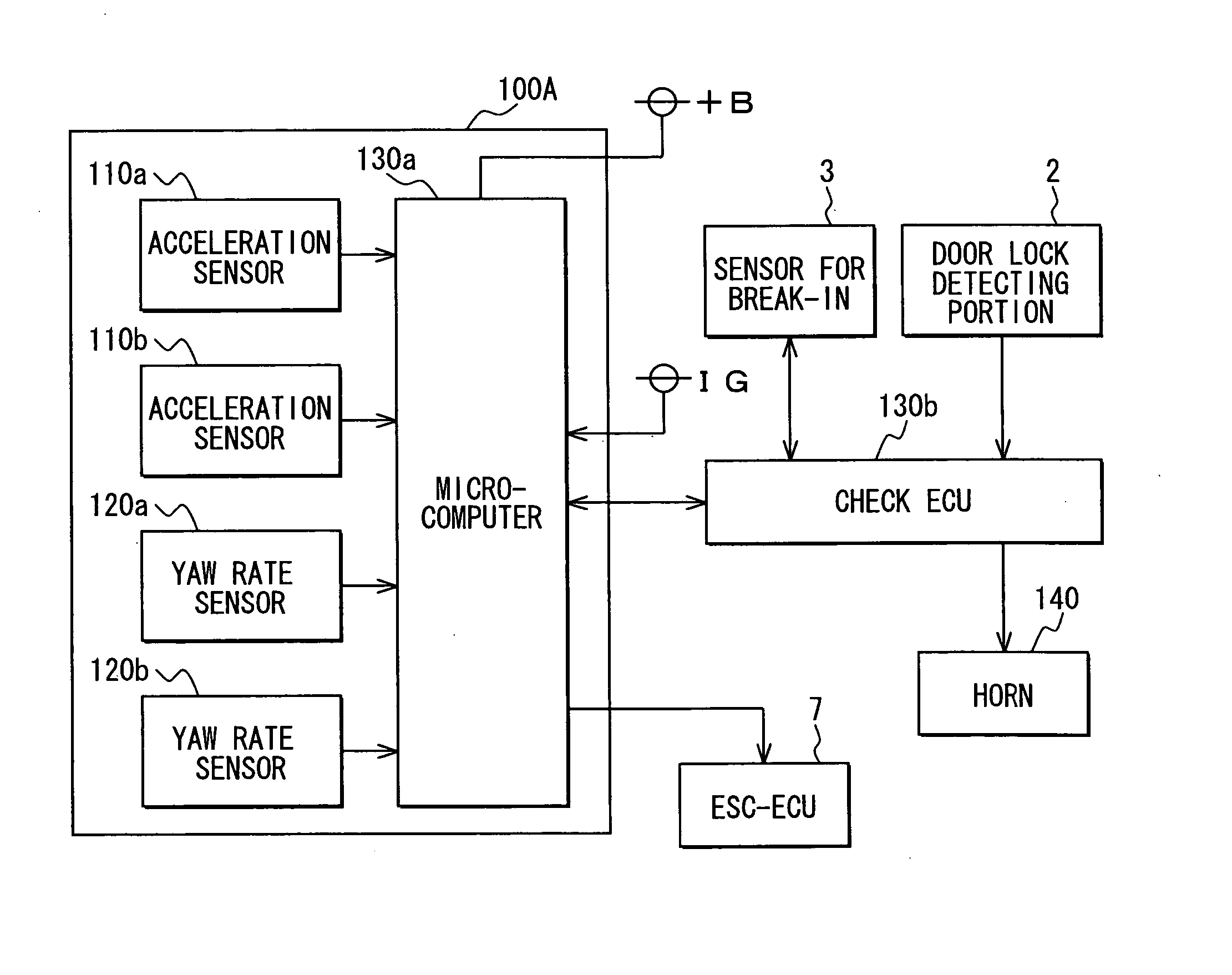
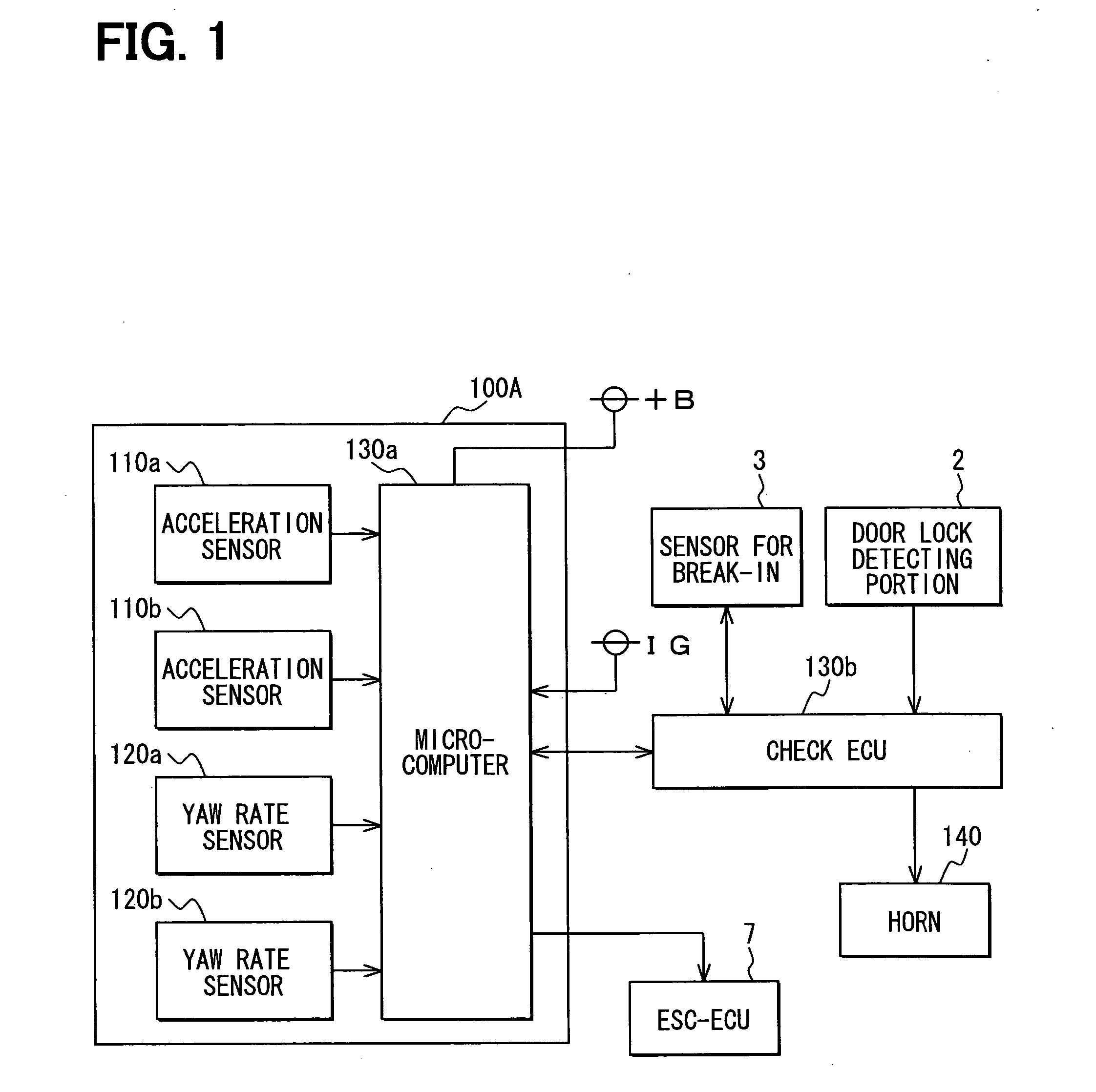
[0052] As shown in FIG. 1, an automotive antitheft system has an inclination sensor device 100A, a detecting portion 2 for a door lock device, a sensor 3 for break-in, a check ECU 130b, and a horn 140 as a warning device.
[0053] The inclination sensor device 100A is composed of an inertia sensor having multiple acceleration sensors 110a, 110b, multiple yaw-rate sensors 120a, 120b, and a micro-computer 130a. The inertia sensor is also used in an anti-lock braking system for a vehicle. Namely, the inertia sensor is commonly used for the anti-lock braking system and the antitheft system.
[0054] The acceleration sensors 110a, 110b detect acceleration in two orthogonal directions in a horizontal plane of a vehicle, for example a longitudinal direction (front-back direction) of the vehicle and a cross direction (right-left direction). The acceleration sensor 110a outputs a detectin...
second embodiment
[0086] A second embodiment of the present invention will be explained with reference to the accompanying drawings (FIGS. 4 to 9). In the drawings, letters F, B, L and R respectively designate a front, a back, a left, and a right direction.
(Structure of Inclination Sensor)
[0087] As shown in FIG. 4, an inclination sensor 100B is composed of detecting elements 110R, 110L, a micro-computer 130c, a printed circuit board 11 on which electrical parts and components are mounted, and a module casing 14 for accommodating the printed circuit board 11. In FIG. 4, the module casing having a box shape is shown, in which a top portion is removed.
[0088] Each of the detecting elements 110R, 110L is made of such a sensor element for detecting an inclination in a certain direction. For example, the detecting element 110R, 110L has a detecting portion (not shown) of an electrostatic capacitor type, which is formed as a beamed structure in a semiconductor substrate having multiple fixed and movable ...
third embodiment
[0130]FIG. 10 is a schematic block diagram showing an antitheft apparatus 10 for a vehicle, according to a third embodiment of the present invention.
[0131] As shown in FIG. 10, the antitheft apparatus 10 is composed of an acceleration sensor 110, an angular speed sensor 120, an electronic control unit (ECU) 130, a warning device 140, and an information transmitting device 140.
[0132] The acceleration sensor 110 detects an acceleration of the vehicle and outputs a signal depending on the acceleration. A detecting principle, a number of detecting axis, and a number of sensors are not limited to specific values. For example, a sensor of a piezoelectric type, an electrostatic capacitance type, an electromagnetic type, a gas (thermo-type) type, and so on can be used in the invention. According to the embodiment, the acceleration sensor 110 is formed as to detect accelerations in two directions, namely in an X axis, which is a cross direction (left-right direction) of the vehicle, and in...
PUM
 Abstract
Description
Claims
Application Information