Antenna structure for the radio frequency identification tag

an antenna structure and radio frequency identification technology, applied in the field of antenna structure for radio frequency identification tags, can solve the problems of high manufacturing cost, inconvenient use, extra large etc., and achieve the effect of reducing the size of the rfid tag and production cos

Inactive Publication Date: 2007-05-10
WHA YU IND CO LTD
View PDF2 Cites 7 Cited by
  • Summary
  • Abstract
  • Description
  • Claims
  • Application Information

AI Technical Summary

Benefits of technology

[0010] 1. The present invention arranges the first and second radiating body 21, 22 of the antenna 20 in coiled form on the carrier 10 to effectively

Problems solved by technology

While attempting to achieve optimal data transmission efficiency, the antenna length of the RFID Tag may result in an extra l

Method used


Image

  • Antenna structure for the radio frequency identification tag
  • Antenna structure for the radio frequency identification tag
  • Antenna structure for the radio frequency identification tag

Examples


Embodiment Construction

[0019] The features and the advantages of the present invention will be more readily understood upon a thoughtful deliberation of the following detailed description of a preferred embodiment of the present invention with reference to the accompanying drawings.

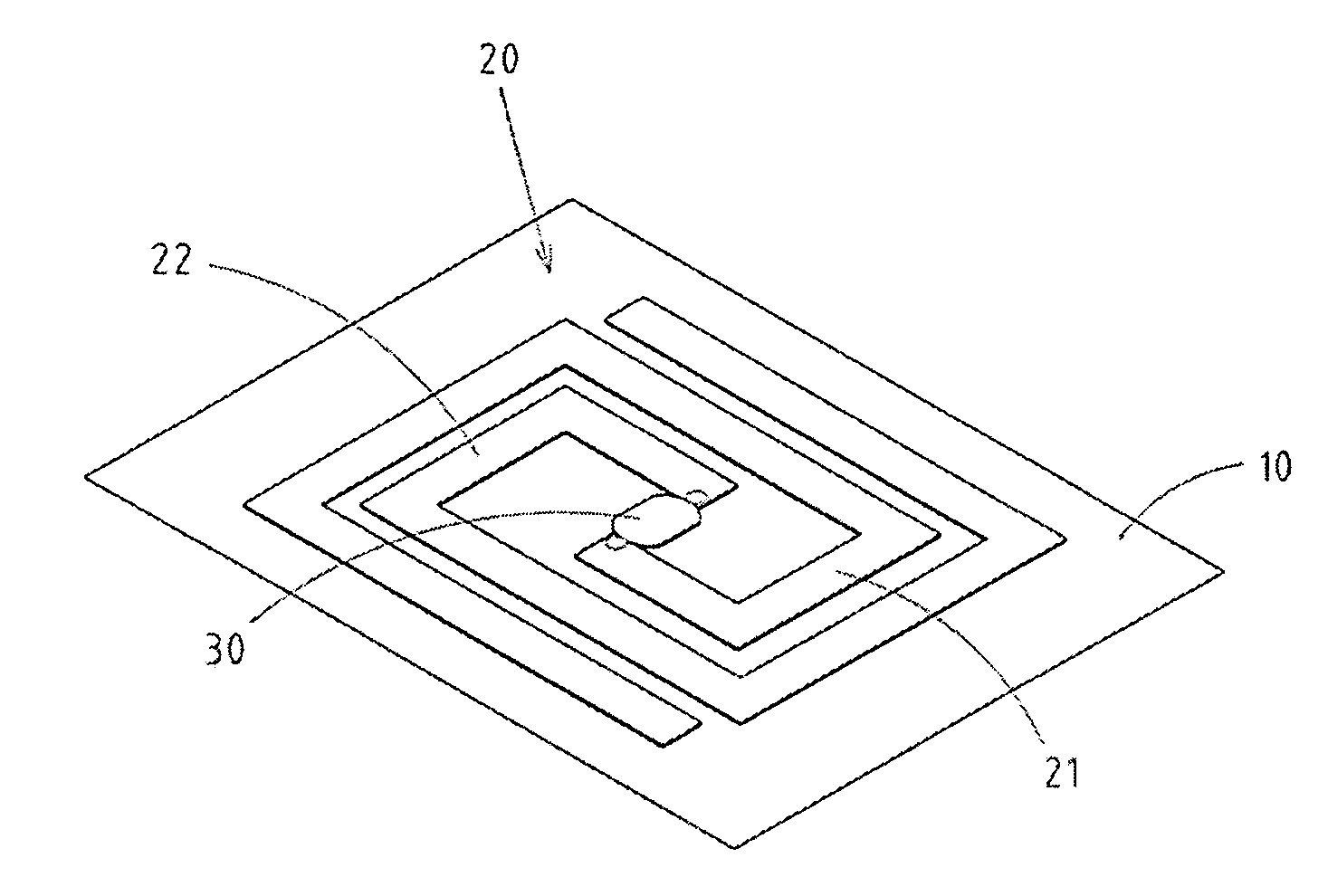
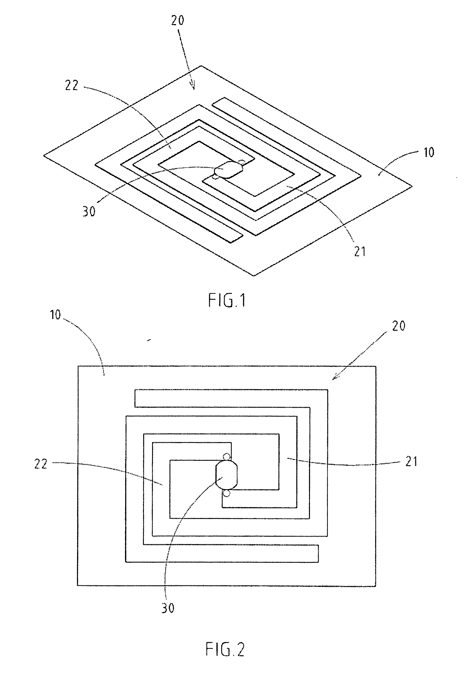
[0020] As shown in FIGS. 1-2, there is a preferred embodiment of the antenna structure for the RFID TAG.

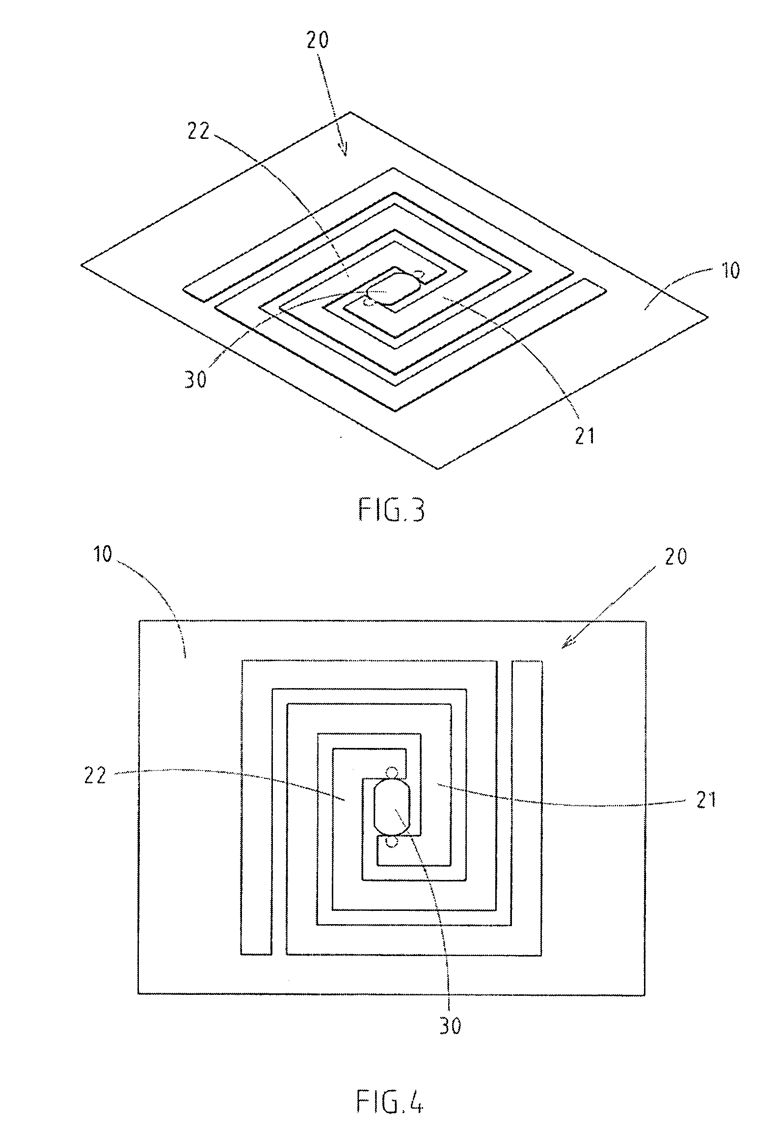
[0021] The invention includes a carrier 10, having an antenna 20 attached to a surface thereof, the antenna 20 being made of conductive material. The antenna 20 is connected to an IC chip 30 electronically. The antenna 20 has a first and second radiating body 21, 22 of the antenna 20 being connected to the IC chip 30 separately. The first and second radiating body 21, 22 are connected to the IC chip and expanded in a coil until a proper length is reached, so that the first and second radiating body 21, 22 is spaced properly to construct a coiled antenna. Thus, the antenna can reduce the size of the RFID Tag and achieve the ...


PUM


Abstract

An antenna structure for the RFID Tag includes a carrier with an antenna attached to a surface thereof, the antenna being made of conductive material. The antenna is connected to an IC chip electronically. The antenna has a first and second radiating body connected to the IC chip separately. The first and second radiating body is connected to the IC chip and expanded in a coil until a proper length is reached. Thus, the first and second radiating body is spaced properly to construct a coiled antenna.

Description

RELATED U.S. APPLICATIONS [0001] Not applicable. STATEMENT REGARDING FEDERALLY SPONSORED RESEARCH OR DEVELOPMENT [0002] Not applicable. REFERENCE TO MICROFICHE APPENDIX [0003] Not applicable. FIELD OF THE INVENTION [0004] The present invention relates generally to an antenna structure for the radio frequency identification tag (RFID Tag), and more particularly to an antenna with new structure and spatial arrangement. BACKGROUND OF THE INVENTION [0005] The Radio Frequency Identification (RFID) Tag refers to a component comprised of an Integrated Circuit (IC) and antenna. Since the RFID Tag can read or write data from external sources with a RFID reader / writer, it can quickly identify the attributes of an object by wireless data transmission. Users can manage object movement and enhance logistical efficiency. Therefore, the RFID Tag is gradually replacing the conventional barcode and magnetic card. [0006] The length of an antenna for an RFID Tag is determined by wavelength. While atte...

Claims


Application Information

Patent Timeline
IPC IPC(8): G08B13/14
CPCG06K19/07749G06K19/07779G06K19/07783G08B13/2417G08B13/2431
Inventor CHIU, CHIEN-CHIH
Owner WHA YU IND CO LTD
Why Eureka
Try Eureka