Slider and magnetic disk device using the slider

a magnetic disk and slider technology, applied in the direction of recording information storage, maintaining head carrier alignment, instruments, etc., can solve the problems of increasing load on designers, reducing the risk of floating amount, and time-consuming operations for this kind of design change, so as to reduce reduce the risk of floating amount, and limit the change in the amount of floating

Inactive Publication Date: 2007-05-10
WESTERN DIGITAL TECH INC
View PDF13 Cites 8 Cited by
  • Summary
  • Abstract
  • Description
  • Claims
  • Application Information

AI Technical Summary

Benefits of technology

[0018] According to the present invention, the advantageous effect can be obtained to enable designing a slider having reduced changes in the amount of floating due to unevenness of working on the slider, with respect to changes in atmospheric pressure, while limiting the changes in the amount of floating.
[0019] As described above, the present invention has the advantageous effect, by forming a groove configuration surface in a specified shape, to ensure the desired amount of inflow of air flowing to the air bearing surface in a

Problems solved by technology

Also, the high-speed search operation of the actuator during access acts as a cause of inclination of the direction of slide between the slider and the disk and the direction of the air flow below the slider from the longitudinal axis.
In the slider of which constant floating at the magnetic head position is required, there is a risk of the amount of floating being reduced at the minimum-floating-amount position due to a change in the floating attitude of the slider to cause contact between the slider and the disk, i.e., a so-called head crash.
Operations for this kind of design change are time-consuming and the designer needs to have knowledge about fluid dynamics and to be skilled in

Method used


Image

  • Slider and magnetic disk device using the slider
  • Slider and magnetic disk device using the slider
  • Slider and magnetic disk device using the slider

Examples


embodiment 1

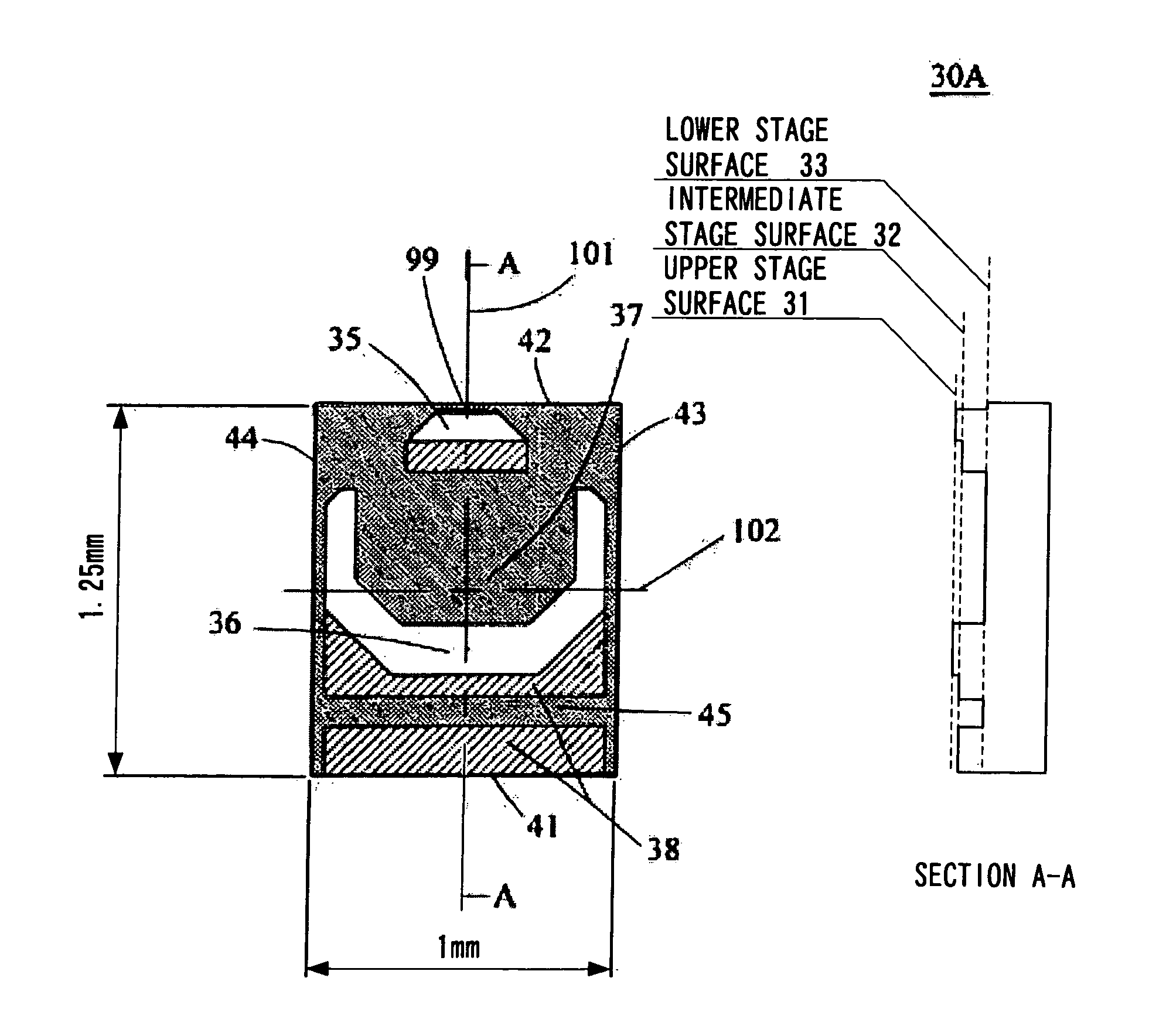
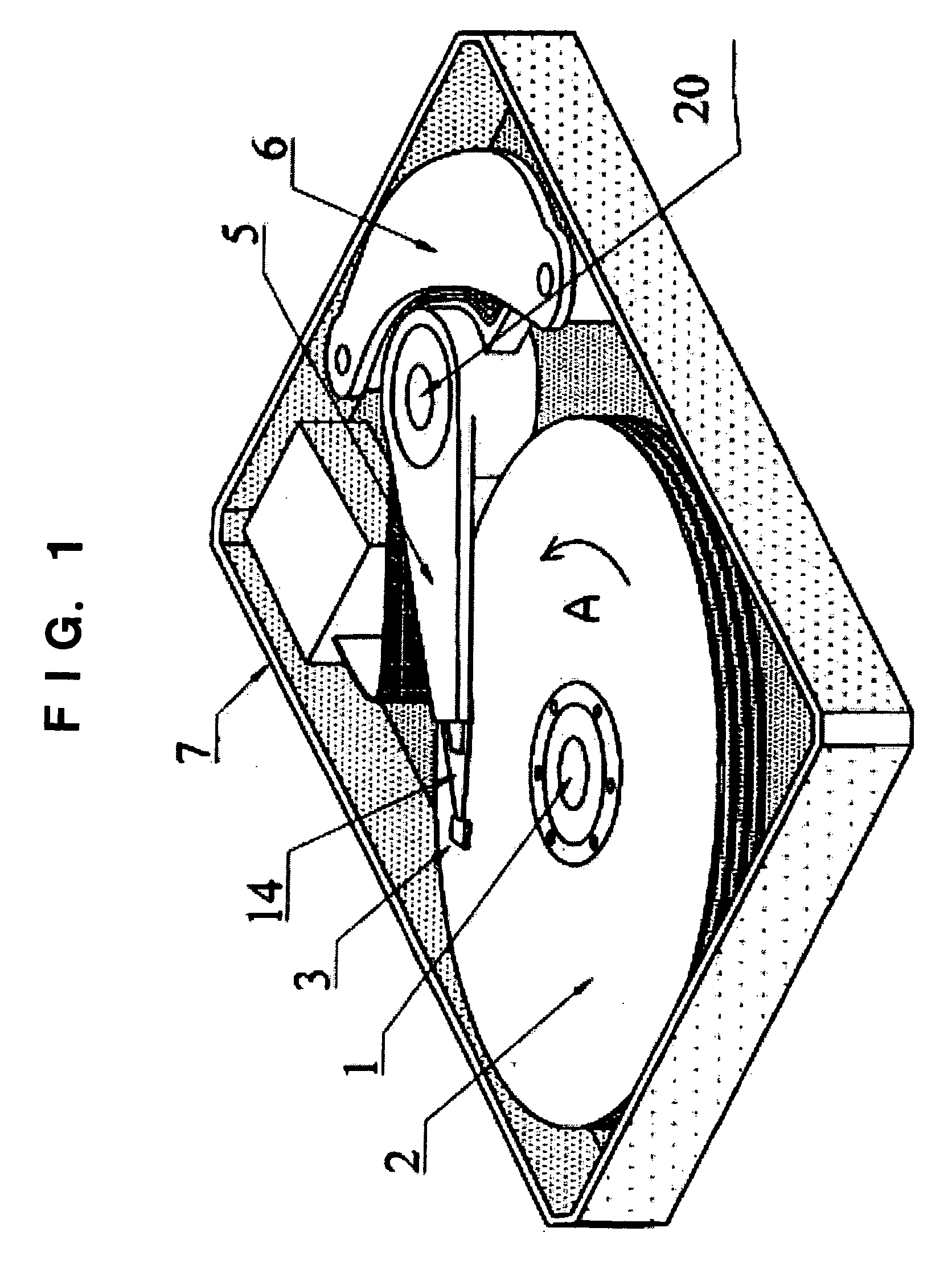
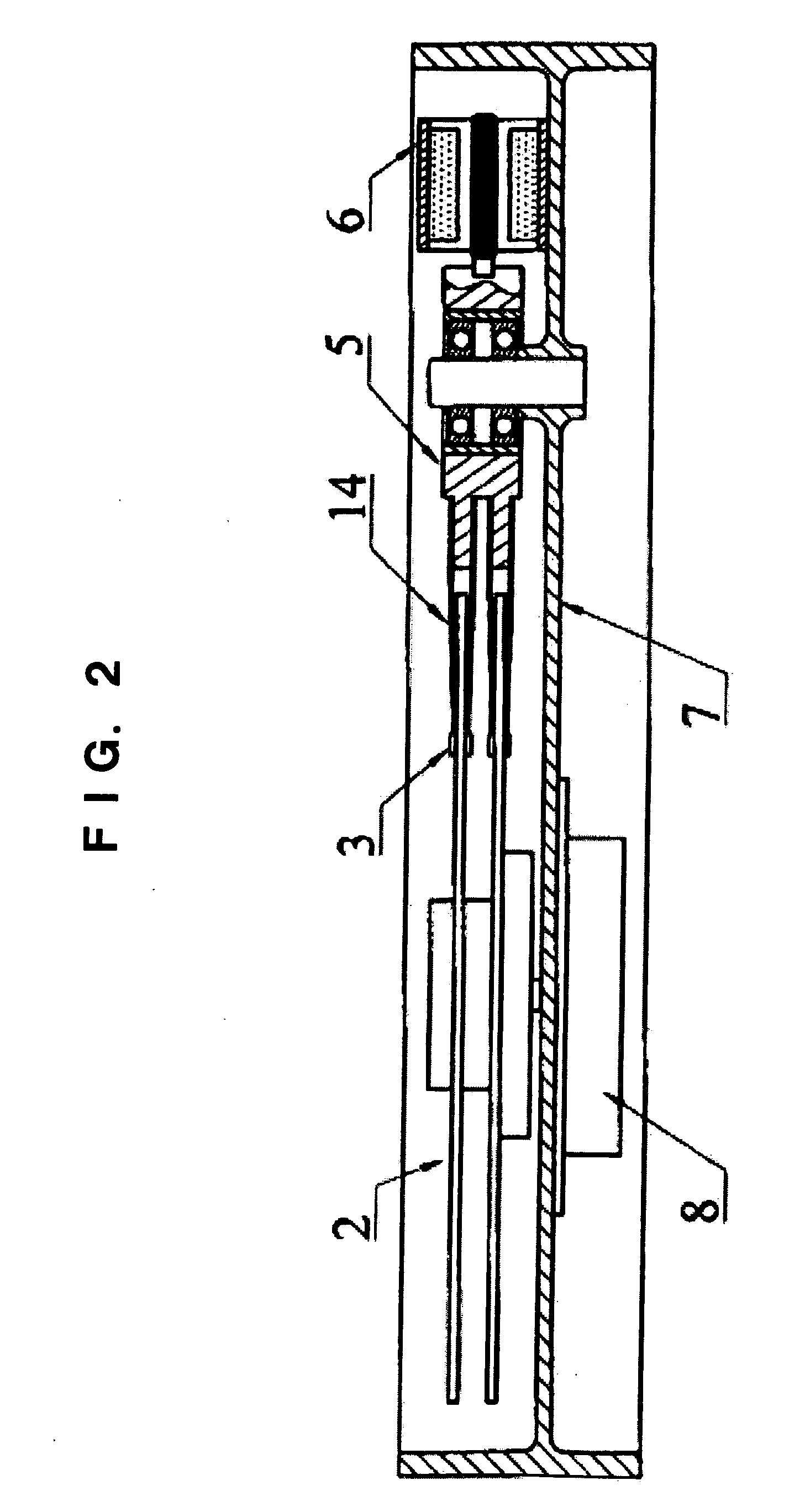
[0052]FIG. 1 is a perspective view of internal portions of a magnetic disk device. FIG. 2 is a sectional view of the magnetic disk device. The magnetic disk device is covered with a housing cover (not shown). Suspensions 14 are respectively attached to distal ends of actuator arms 5 rotatably attached to an actuator shaft 20. A slider 3 carrying a magnetism converter or a read / write head 99 (not shown in FIG. 1) is attached to a distal end of each suspension 14.

[0053] A spindle 1 is provided in a housing 7. A plurality of disks 2 are rotatably attached to the spindle 1 while being spaced apart from each other. The disks 2 are rotated in a direction of arrow A by the spindle 1 rotated by a motor 8. Information is written to each disk 2 or read from the disk 2 by the head 99 (not shown) existing in the slider 3 and positioned by the actuator arm 5.

[0054] A torque is applied to the actuator arms 5 by a voice coil motor 6 to rotate the actuator arms 5 on the actuator shaft 20.

[0055] ...


PUM


Abstract

A slider having an improved atmospheric pressure variation characteristic can be provided by ensuring the desired amount of inflow of air flowing to the air bearing surface in a region where it is difficult to ensure the desired air inflow amount, e.g., a region where the slider/disk relative speed is low or a region where the area of the air bearing surface is small by forming a groove configuration surface in a specified shape. In the negative pressure utilization type slider, a groove configuration surface lower in height than an air in flow surface is formed between the disk inner peripheral end and the disk outer peripheral end of the air inflow surface in the air flow incoming end side of a pressure generating surface, separately from a negative pressure generating surface.

Description

TECHNICAL FIELD [0001] The present invention relates to a slider and a data recording disk device and, more particularly, to a slider with an air bearing surface configuration suitable for a data recording disk device in which the slider is supported on a rotary actuator, and to a data recording disk device using the slider. Devices denoted by “data recording disk device” include a device having one of a data recording function and a data reproducing function, and a device having both of these functions. BACKGROUND ART [0002] In recent years, the data recording density in magnetic disk devices has been remarkably increased. The rate of increase in recording density in magnetic disk devices is said to be 100% per year. With the remarkable increase in data recording density, a quantum leap has been achieved in data recording capacity of magnetic disk devices. The increase in data recording capacity has accelerated the reduction in size of magnetic disk devices, and cost-effective magn...

Claims


Application Information

Patent Timeline
IPC IPC(8): G11B5/60G11B21/21
CPCG11B5/6005G11B21/21G11B5/6082
Inventor NAKAKITA, MASARUTAKAGI, SUSUMU
Owner WESTERN DIGITAL TECH INC
Why Eureka
Try Eureka