Cooling apparatus for flat display device
- Summary
- Abstract
- Description
- Claims
- Application Information
AI Technical Summary
Benefits of technology
Problems solved by technology
Method used
Image
Examples
first embodiment
[0037] [FIRST EMBODIMENT]
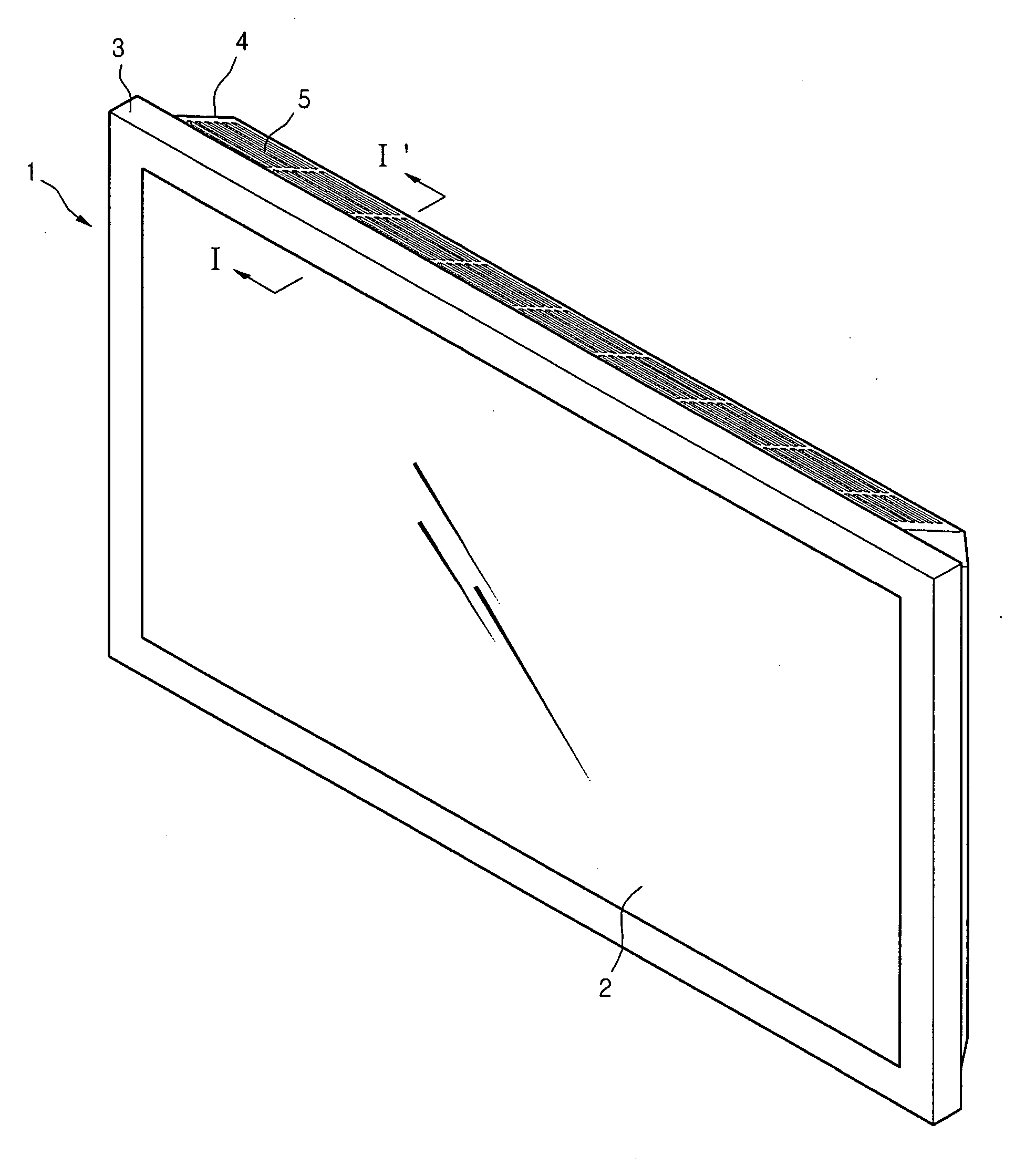
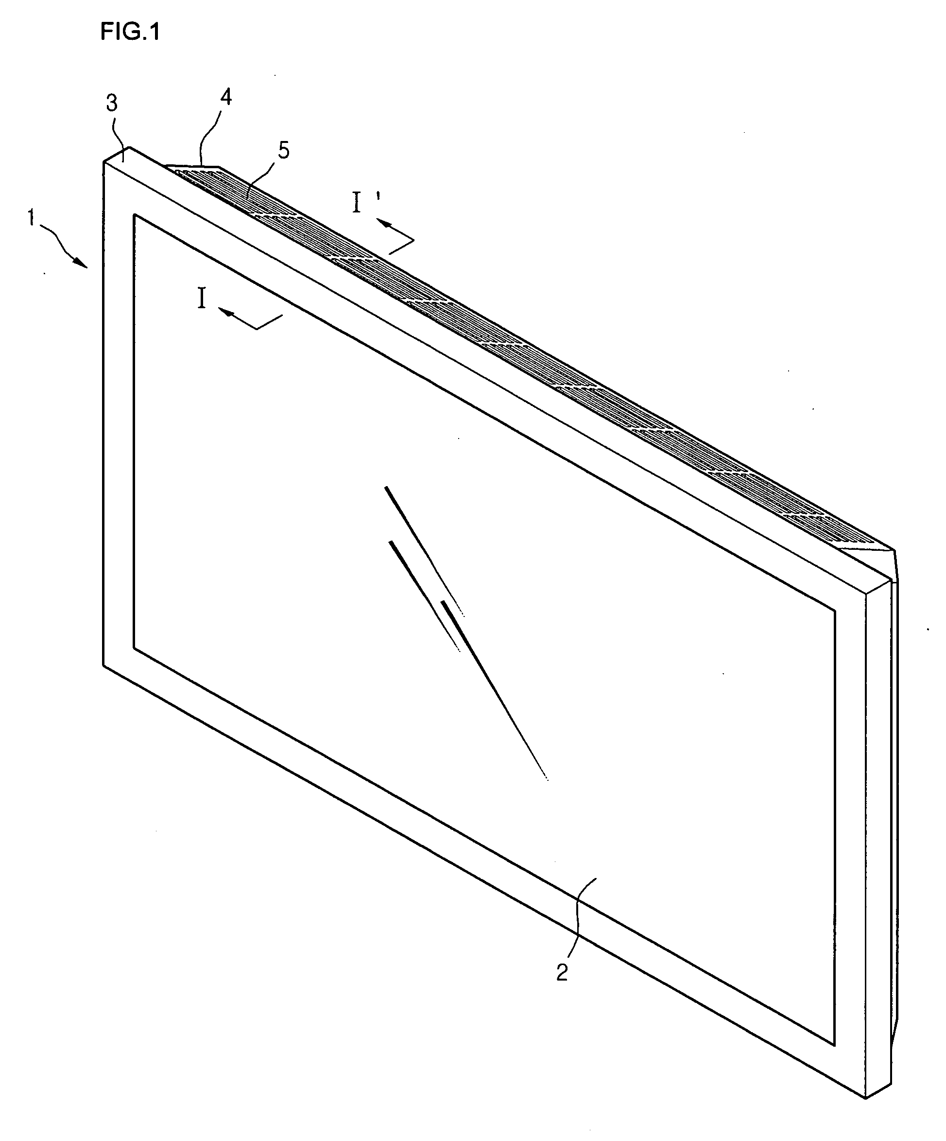
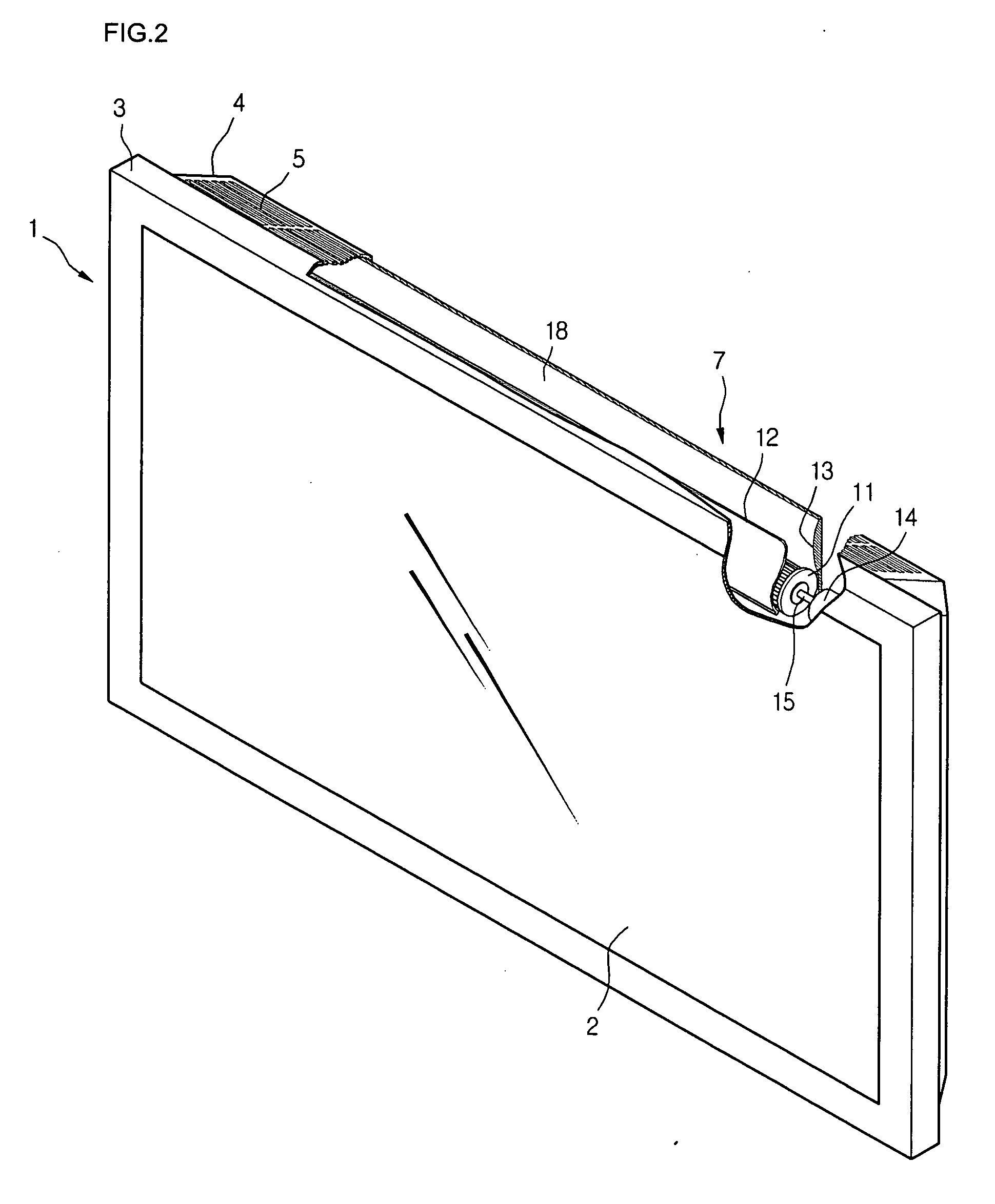
[0038]FIG. 1 is a perspective view of a flat display device according to an embodiment of the present invention.
[0039] Referring to FIG. 1, a flat display device 1 of this embodiment includes a flat display module 2, a front cover 3 for supporting and protecting a front portion of the flat display module 2, and a back cover 4 for supporting and protecting a rear portion of the flat display module 2. An air outlet 5 through which internal hot air of the flat display device 1 is exhausted is formed on an upper frame of the back cover 4. The air outlet 5 has a plurality of slits. The slits are arranged not to deteriorate strength of the back cover 4. That is, the slits are collected in an area of the air outlet 5.
[0040] The flat display module 2 may be selected from the group consisting of an LCD, an FED, a PDP, and an EL. Preferably, the flat display module 2 may be the PDP generating high temperature heat.
[0041] The front and back covers 3 and 4 define a s...
second embodiment
[0069] [SECOND EMBODIMENT]
[0070]FIG. 6 is a rear view of a flat display device according to another embodiment of the present invention. The flat display device of this embodiment is substantially identical to that of FIG. 1 except for the locations of the air inlet and outlet.
[0071] Referring to FIG. 6, an air inlet 21 is formed on an upper inclined portion of the back cover 4 while an air outlet 22 is formed on a lower inclined portion of the back cover 4. The cross-flow fan 7 is disposed right above the air outlet 22.
[0072] According to this embodiment, it cannot be expected to realize the airflow by the natural convection. However, since the hot air is exhausted downward, the possibility of directing the hot air to the user can be reduced. Furthermore, when the disposition of the components that require the thermal stability or generate high heat is limited due to a circuit arrangement of the flat display module 2, the locations of the air inlet and outlet can be properly adju...
third embodiment
[0074] [THIRD EMBODIMENT]
[0075]FIG. 7 is a rear view of a flat display device according to another embodiment of the present invention. The flat display device of this embodiment is substantially identical to that of FIG. 6 except for the locations of the air inlet and outlet.
[0076] Referring to FIG. 7, an air inlet includes first and second inlet portions 31 and 32 that are respectively formed on upper and lower inclined portions of the back cover 4. An air outlet 33 is formed on a left portion (when viewed from a front portion of the display device).
[0077] Therefore, external air introduced through the upper and lower portions of the flat display device is exhausted through the air outlet 33 formed on the left frame portion.
[0078] According to this third embodiment, a degree of freedom in arranging the circuit of the flat display device can be improved. Likewise the foregoing embodiments, hot air is not directed toward the user. Furthermore, since the external cool air can be i...
PUM
 Abstract
Description
Claims
Application Information
 - R&D
- Intellectual Property
- Life Sciences
- Materials
- Tech Scout
- Unparalleled Data Quality
- Higher Quality Content
- 60% Fewer Hallucinations
Browse by: Latest US Patents, China's latest patents, Technical Efficacy Thesaurus, Application Domain, Technology Topic, Popular Technical Reports.
© 2025 PatSnap. All rights reserved.Legal|Privacy policy|Modern Slavery Act Transparency Statement|Sitemap|About US| Contact US: help@patsnap.com


