Remote sensing system capable of coregistering data from sensors potentially having unique perspectives

a remote sensing and data technology, applied in scene recognition, instruments, optics, etc., can solve the problems of deteriorating image position accuracy, distortion of lens, and objects in the image appearing closer or further from each other than they really ar

Active Publication Date: 2007-05-10
INTERGRAPH
View PDF13 Cites 22 Cited by
  • Summary
  • Abstract
  • Description
  • Claims
  • Application Information

AI Technical Summary

Problems solved by technology

However, complexities permeate this relationship, including accounting for Earth's generally curved surface and the flatness of the light-collecting surfaces of sensors, film, images and maps; the distortion created by optical systems such as lenses; and the unique position and orientation (and therefore unique perspective) sensors have in a remote-sensing system.
Lens distortion deteriorates the positional accuracy of image points located on the image plane and occurs when light rays passing through the lens are imprecisely bent, thereby changing the relative ray directions such that the light rays intersect the image plane at deviant positions.
As a result, objects in the image will appear distorted or closer or further from each other than they really are.

Method used


Image

  • Remote sensing system capable of coregistering data from sensors potentially having unique perspectives
  • Remote sensing system capable of coregistering data from sensors potentially having unique perspectives
  • Remote sensing system capable of coregistering data from sensors potentially having unique perspectives

Examples


Embodiment Construction

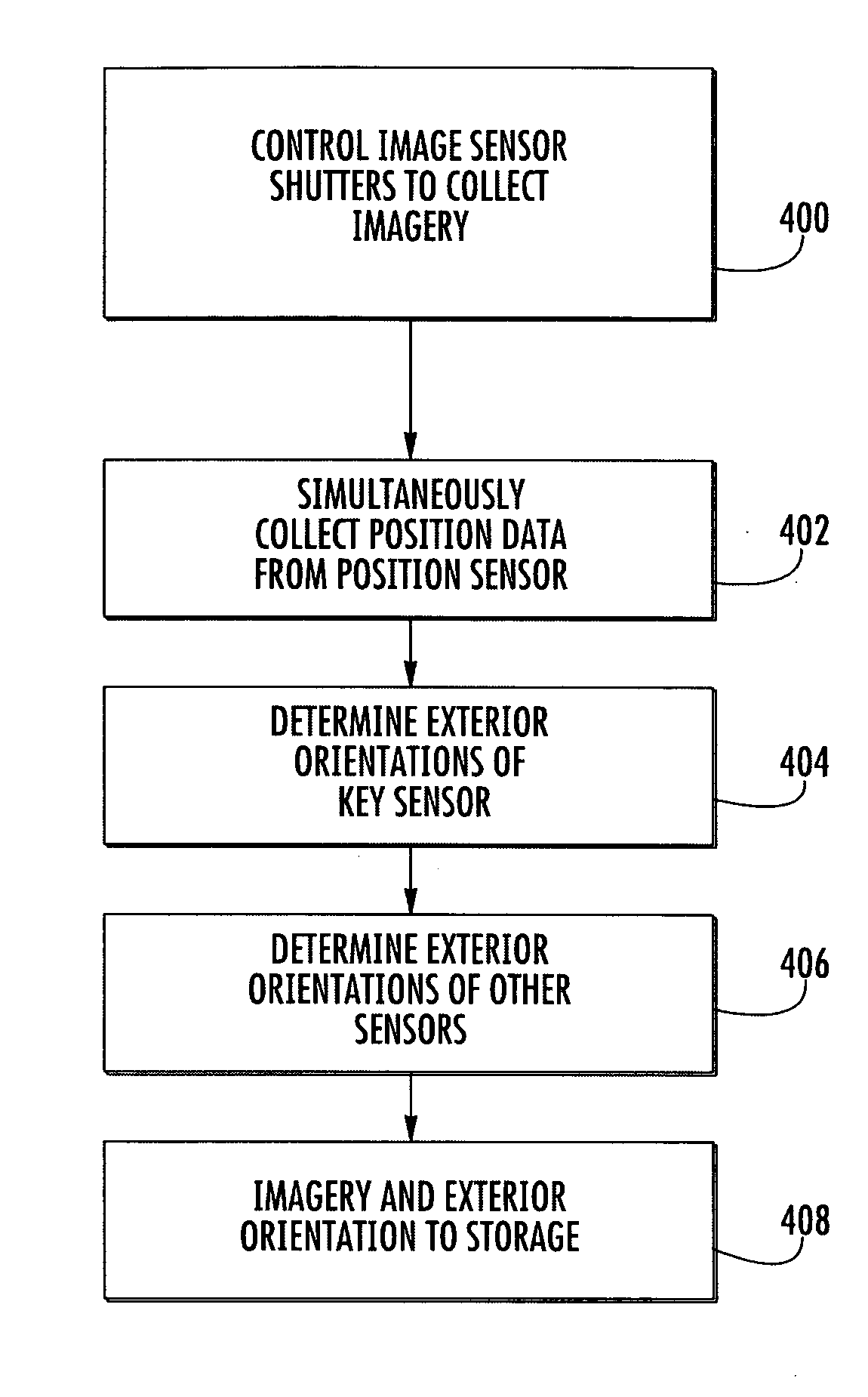
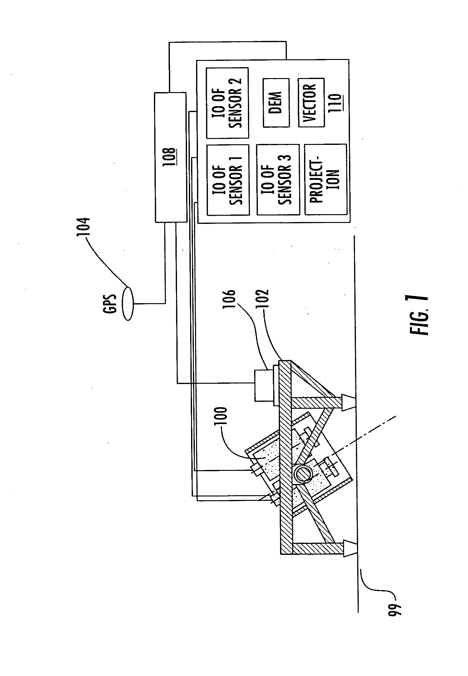
[0019] As shown in FIG. 1, the aerial mapping system of the preferred embodiment includes an aircraft 99 carrying a plurality of image sensors 100 and processing equipment. The plurality of image sensors 100 are mounted on a platform or frame 102 that is in turn mounted to the aircraft. Each of the sensors could be produced by different manufacturers and be designed to collect light from the same or various bands in the electromagnetic spectrum such as infrared, ultraviolet, visible-light, and other bands of electromagnetic wavelengths. In addition, each sensor could have the same or a different footprint on the ground from the other sensors, although the sensors are preferably fixed in the aircraft in such a way that 60 to 80% of the footprints overlap during a flight (even if the distance between the ground and the aircraft during the flight varies to some extent). In addition to having different footprints, each sensor may have unique interior orientation parameters owing to its ...


PUM


Abstract

An aerial imaging system includes a platform capable of moving through the air, a spatial sensor, a plurality of image sensors mounted to the platform and a computer. The spatial sensor collects position data indicating the position of the platform. The plurality of image sensors includes a key sensor and at least one non-key sensor. The computer includes a storage device and a processor configured to execute instructions comprising the steps of (i) controlling the plurality of image sensors to collect image data simultaneously, (ii) determining the exterior orientation of the key sensor based on the position data, and (iii) determining the exterior orientation of at least one non-key sensor based on the exterior orientation of the key sensor.

Description

CROSS REFERENCE TO RELATED APPLICATION [0001] This application claims the benefit of U.S. provisional patent application No. 60 / 735,428, filed Nov. 10, 2005.BACKGROUND OF THE INVENTION [0002] The present invention relates generally to remote sensing. Remote sensing can be defined as the science of deriving information about Earth's land and water areas from images acquired at a distance. It usually relies upon measurement of electromagnetic energy reflected by or emitted from the features of interest. [0003] Remote sensing typically uses an electromagnetic sensor such as a camera (often a digital camera) or radar device, an airborne platform carrying the electromagnetic sensor and a position and attitude sensor. [0004] In order to use the imagery collected by the electromagnetic sensor, one must establish the relationship among the camera or sensor used to capture imagery, the imagery itself, and the ground. However, complexities permeate this relationship, including accounting for ...

Claims


Application Information

Patent Timeline
Patent Type & Authority Applications(United States)
IPC IPC(8): G06K9/00G06V20/13
CPCG01C11/02G03B15/006G06K9/0063G06T17/05G06V20/13
Inventor HOLCOMB, DERROLD WAYNE
Owner INTERGRAPH
Why Eureka
Try Eureka