Radio control helicopter toy

a technology of radio control and helicopter, applied in the direction of toys, remote control toys, entertainment, etc., can solve the problems of increased cost as a whole, inability to rotate, and complicated structure, and achieve the effect of preventing the turnover of aircra

Inactive Publication Date: 2007-05-10
TAIYO KOGYO CORPORATION
View PDF2 Cites 86 Cited by
  • Summary
  • Abstract
  • Description
  • Claims
  • Application Information

AI Technical Summary

Benefits of technology

[0011] In the fifth aspect of the present invention, a tail pipe is mounted on the rear side of the above-mentioned airframe and a tail rotor to be driven by a tail motor is mounted on an end part of the tail pipe. With the tail rotor, the airframe turnover can be prevented as well as the airframe can be controlled in the right and left directions.
[0012] In the sixth aspect of the present invention, the magnet or the ferromagnetic material mounted on the above-mentioned rotor head of the above-mentioned blade inclining mechanism is formed in a ring-like shape surrounding the rotation center of the above-mentioned mast. Since the magnet or the ferromagnetic material mounted on the rotor head is formed in a ring-like shape, the blade surface inclination of the rotor blade can be controlled certainly.
[0013] Since a mast mounted on the upper side of an airframe so as to be rotated by a main motor loaded on the airframe, a rotor moun

Problems solved by technology

However, since the outside part is connected with an actuator mounted on the airframe for controlling the inclining of the swash plate with a link, it cannot be rotated.
Therefore, a highly sophisticated part such as a ball bearing is required for the inside and the outside

Method used


Image

  • Radio control helicopter toy
  • Radio control helicopter toy
  • Radio control helicopter toy

Examples


Embodiment Construction

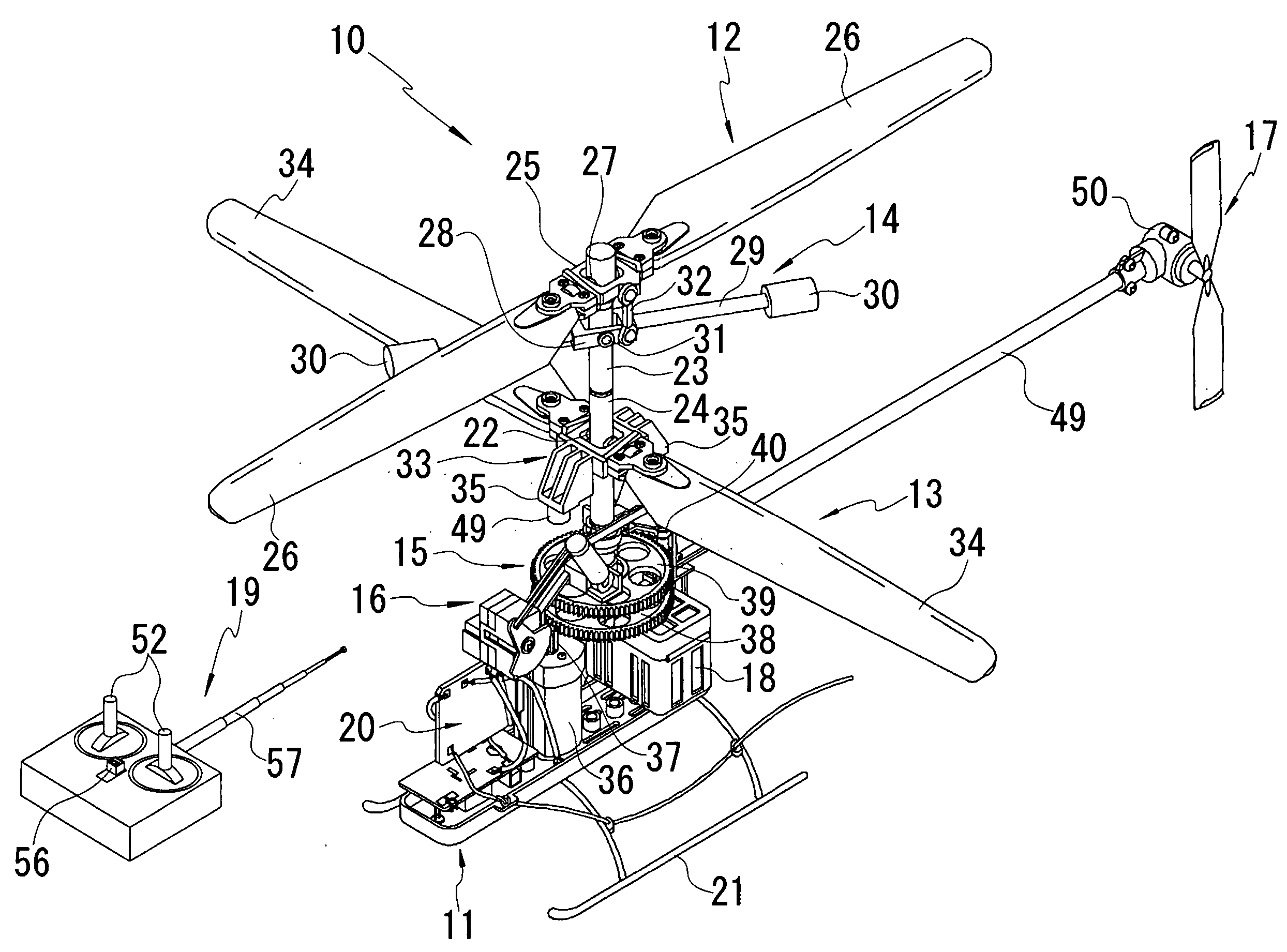
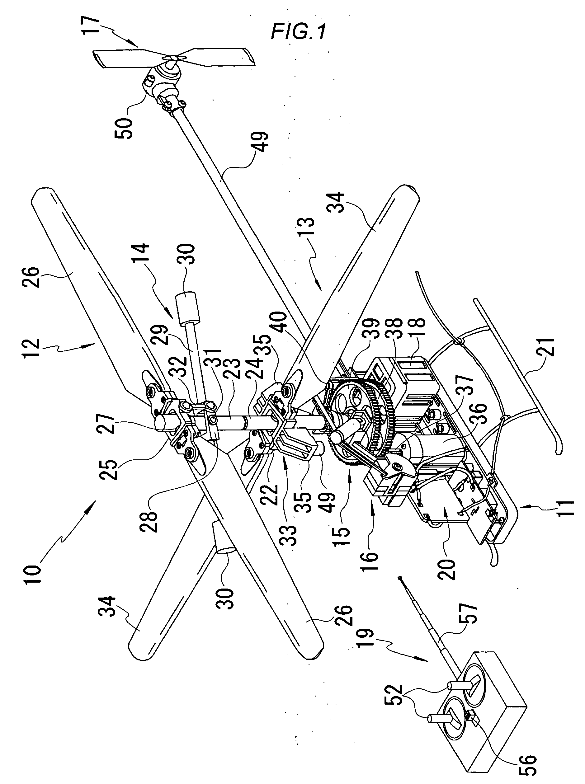
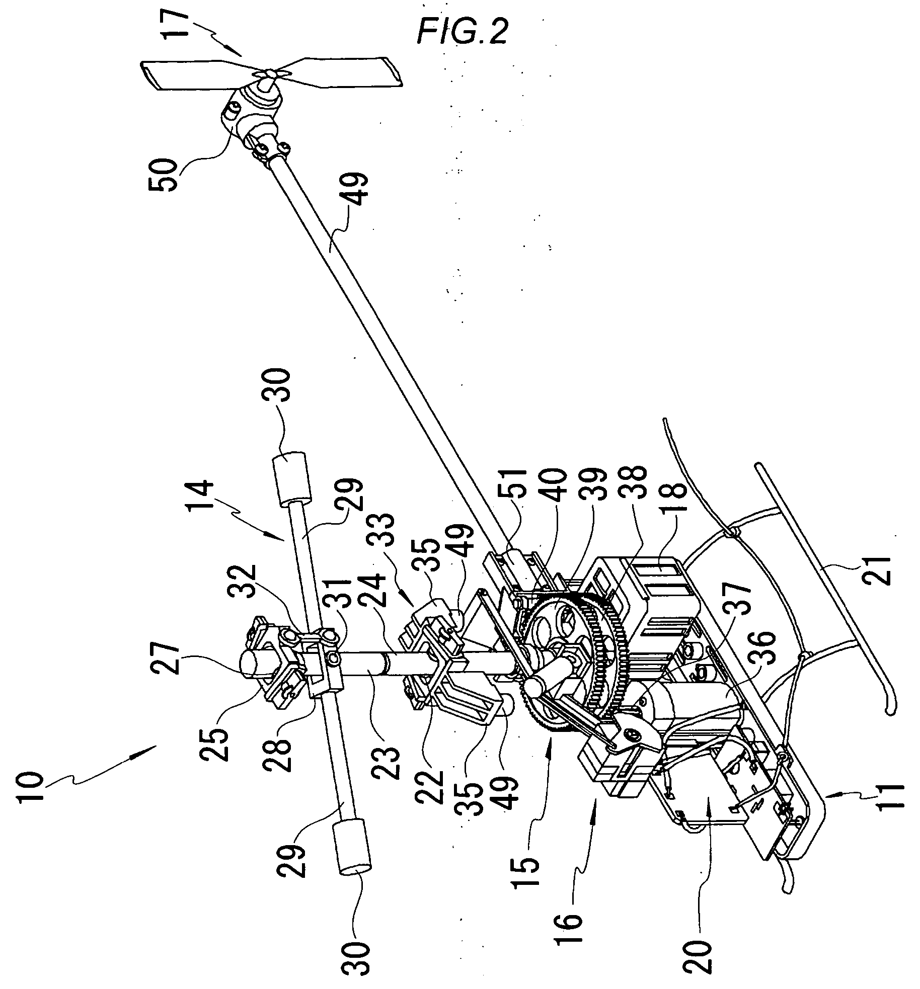
[0019] Hereinafter, the present invention will be explained specifically with reference to an embodiment shown in the figures. FIGS. 1 to 5 are diagrams for explaining a radio control helicopter toy of an embodiment of the present invention. FIG. 1 is a perspective view for explaining the entire configuration of a radio control helicopter toy, FIG. 2 is a perspective view for explaining a blade inclining mechanism of a radio control helicopter toy, FIG. 3 is a side view for explaining a blade inclining mechanism of a radio control helicopter toy, FIG. 4 is a perspective view of a blade inclining mechanism part of a radio control helicopter toy, and FIG. 5 is a block diagram for explaining the control operation of a radio control helicopter toy.

[0020] In these figures, the radio control helicopter toy 10 of this embodiment includes an airframe 11, an upper rotor 12 and a lower rotor to be rotated concentrically in the opposite directions, provided in the upper part of the airframe, ...


PUM


Abstract

The present invention provides a radio control helicopter toy including a mast mounted projecting to the upper side of an airframe so as to be rotated by a main motor, a rotor mounted on the upper part of the mast via a rotor head with the blade surface of a rotor blade capable of inclining, a blade inclining mechanism having an arm with one end part side thereof mounted rotatably on the airframe side and the other end part side thereof is mounted to be driven to approach to the above-mentioned rotor head side by an actuator, for inclining the blade surface of the above-mentioned rotor by the magnetic force generated between magnets mounted on the end part of the arm and the above-mentioned rotor head or between a magnet and a ferromagnetic material, and a receiver loaded on the above-mentioned airframe for controlling the operation of the above-mentioned main motor and the actuator.

Description

BACKGROUND OF THE INVENTION [0001] 1. Field of the Invention [0002] The present invention relates to a radio control helicopter toy, the movement control thereof is performed with remote control. [0003] 2. Description of the Related Art [0004] Conventionally, for the movement control of a helicopter, movement can be made in front and back, right and left directions by inclining the blade surface of a rotor provided on the aircraft. For inclining the blade surface of such a rotor, in the real helicopter, a mechanism for inclining the blade surface by interlocking a swash plate, rotating together with the rotor, with the blade via a link is adopted. This kind of the rotor blade surface inclining mechanism by a swash plate is adopted also for a movement control for a helicopter toy. For example, a technique related to a radio control helicopter with co-axial rotors, that is upper and lower rotor heads rotating in the opposite directions are provided concentrically, wherein the inclinin...

Claims


Application Information

Patent Timeline
IPC IPC(8): A63H27/127
CPCA63H27/12A63H30/04
Inventor GOTOU, TAKEOOHE, YOSHIAKIITOU, TETSUYA
Owner TAIYO KOGYO CORPORATION
Why Eureka
Try Eureka