
Architecture of future open wireless architecture (OWA) radio system

a radio system and open technology, applied in the field of open architecture of future radio systems, can solve problems such as problems for subscribers, wireless network operators and equipment vendors, and problems for wireless network operators, and achieve the effect of solving problems for network operators, avoiding interference, and avoiding interferen

Inactive Publication Date: 2007-05-10
PALO ALTO RES
View PDF2 Cites 64 Cited by
  • Summary
  • Abstract
  • Description
  • Claims
  • Application Information

AI Technical Summary

Benefits of technology

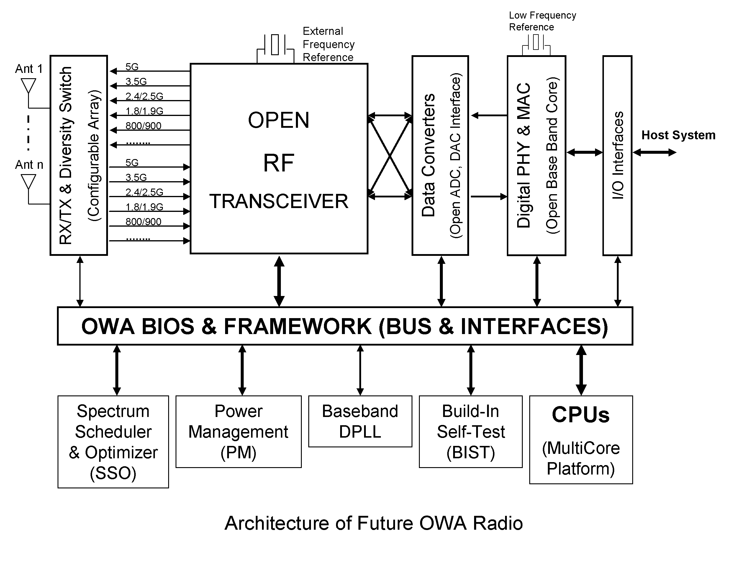
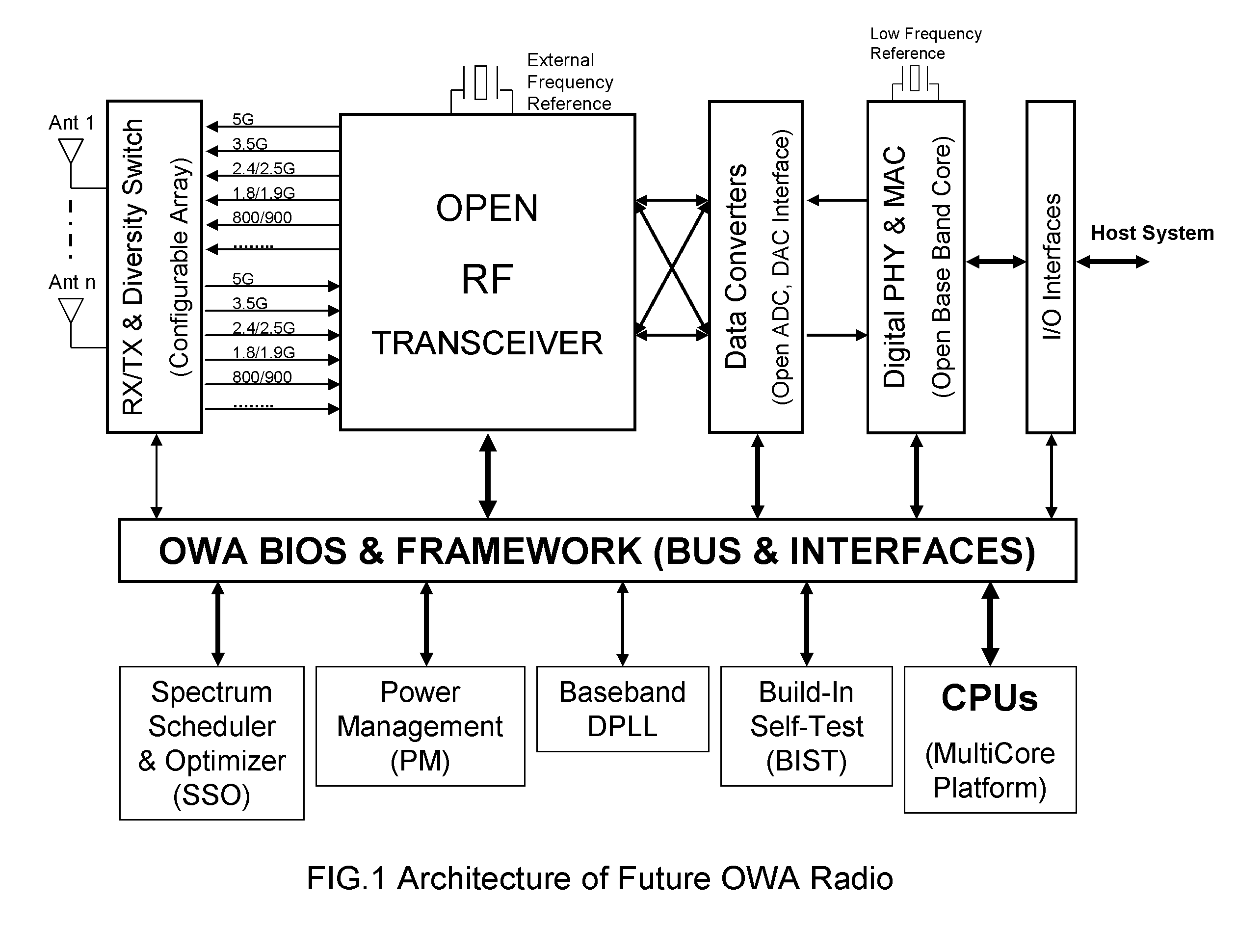
[0019] The architecture of future open wireless architecture (OWA) radio system of the present invention incorporates an OWA BIOS (basic input / output system) AND FRAMEWORK architecture which defines the open bus and interfaces architecture to manage the “plug and playopen architecture of the whole OWA radio systems, as well as provides the extensibility and upgradeability of the different system units and functional modules.

Problems solved by technology

With the proliferation of wireless standards in television, radio and mobile communications, compatibility issues have emerged in wireless networks and systems.
Inconsistency between wireless standards is causing problems to subscribers, wireless network operators and equipment vendors.
Network operators face the dilemma during the upgrade of a network from one generation to another due to the presence of a large number of subscribers using legacy handsets incompatible with newer generations of standards.
Equipment vendors face difficulty in airing new technology because of short time-to-market requirements.
Inconsistency between wireless standards is inhibiting deployment of global roaming facilities and causing problems in introducing new features and services.
Traditional wireless systems, with their capabilities hard-coded in them, are no longer able to keep step with this brisk growth rate.
However, SDR is only a radio in which the operating parameters including inter alia frequency range, modulation type, and / or output power limitations can be set or altered by software.
In other words, SDR consumes much more power and spectrum in exchange of the system flexibility.
From the business point of view, SDR is not a cost-effective solution in commercial wireless communications.
However, cognitive radio is not an open system from the architecture point of view, and does not meet the requirements of the open system definition.

Method used


Image

  • Architecture of future open wireless architecture (OWA) radio system
  • Architecture of future open wireless architecture (OWA) radio system
  • Architecture of future open wireless architecture (OWA) radio system

Examples


Embodiment Construction

[0033] The present invention relates to an implemental and commercial multi-band common wireless and mobile communication platform for the future open wireless architecture radio system.

[0034]FIG. 1 is the architecture of future OWA radio of the present invention. The key system units are: Open RF (Radio Frequency) Transceiver—it converts the high frequency radio signal into the low frequency or intermediate frequency signal, and vice verse. It also demodulates the radio signal into the base-band signal, and vice verse. This transceiver is designed for open architecture which means the whole transmitting and receiving pipes support multi-bands and multi-standards wireless transmission technologies including existing and future over-the-air radio technologies.

[0035] Receiver / Transmitter(RX / TX) and Diversity Antenna Switch—it contains the configurable antenna arrays and the antenna technologies of space and time diversity, including (but not limited to) the smart antenna technology,...


PUM


Abstract

Architecture of future open wireless architecture (OWA) radio system supporting full integration of multi-bands, multi-standards wireless and mobile communication technologies with computer technology based on future open architecture platforms.

Description

BACKGROUND OF THE INVENTION [0001] 1. Field of the Invention [0002] This invention relates to an open architecture of future radio system supporting multi-bands, multi-standards wireless and mobile communications and enabling extensibility and upgradeability of the system modules including, but not limited to, radio frequency transceiver, data converter and base-band processing core, wherein the open system platforms are based on the open wireless architecture (OWA) BIOS (basic input / output system) and framework definitions. This OWA system platform is an optimal integration of future computer architecture with the next generation wireless and mobile communications technology. [0003] 2. Description of the Related Art [0004] With the proliferation of wireless standards in television, radio and mobile communications, compatibility issues have emerged in wireless networks and systems. Inconsistency between wireless standards is causing problems to subscribers, wireless network operator...

Claims


Application Information

Patent Timeline
IPC IPC(8): H04M1/00
CPCH04B1/0003H04B1/406H04W52/288
Inventor LU, WEI
Owner PALO ALTO RES
Learn More