Panel attachment system

a technology of attachment system and panel, which is applied in the direction of hurricane shutters, shutters/movable grilles, building repairs, etc., can solve the problems of unsightly and costly installation, further damage, and high humidity and wood boring insects, and achieve good strength and good economic effects

Inactive Publication Date: 2007-05-17
MUNCH JAMES A
View PDF21 Cites 38 Cited by
  • Summary
  • Abstract
  • Description
  • Claims
  • Application Information

AI Technical Summary

Benefits of technology

[0011] The panels are preferably formed of corrugated sheets of high-impact plastic material, e.g., high density polypropylene or the like. Such corrugated plastic sheet provides good strength due to the thickness and spacing of the corrugations, while still being relatively lightweight. Other types of plastic or composite material may be used as desired, but it has been found that the use of corrugated polypropylene plastic material of about ⅝ inch thickness provides good economy while meeting the ASTM E 1996 and Florida State Building Code requirements. Two or more such panels may be joined edge-to-edge to cover a wider opening by means of an appropriately configured extrusion that grips one panel edge and receives the adjacent panel edge.

Problems solved by technology

While the installation of plywood or similar panels is effective if carried out properly, such wood panels are relatively heavy and cumbersome, and their removal after the storm has passed leaves nail holes in the structure, which can lead to further damage in tropical and subtropical climates having high humidity and wood boring insects.
While shutter systems can be effective, they can also be unsightly and costly to install, and there is often insufficient room to allow the shutters to fold back along the side of the structure.
Moreover, they are not suited for relatively wide spans.
However, such systems known to the present inventor tend to use relatively complex and costly panel configurations (extruded or otherwise specially formed metal, etc.), and / or require special, costly edge components for the panels, which in turn attach to specialized and costly attachment fittings permanently secured to the structure.
Moreover, such systems can be relatively complex and time consuming to install and remove, even though their attachment fittings do not require removal from the building structure.

Method used


Image

  • Panel attachment system
  • Panel attachment system
  • Panel attachment system

Examples


Embodiment Construction

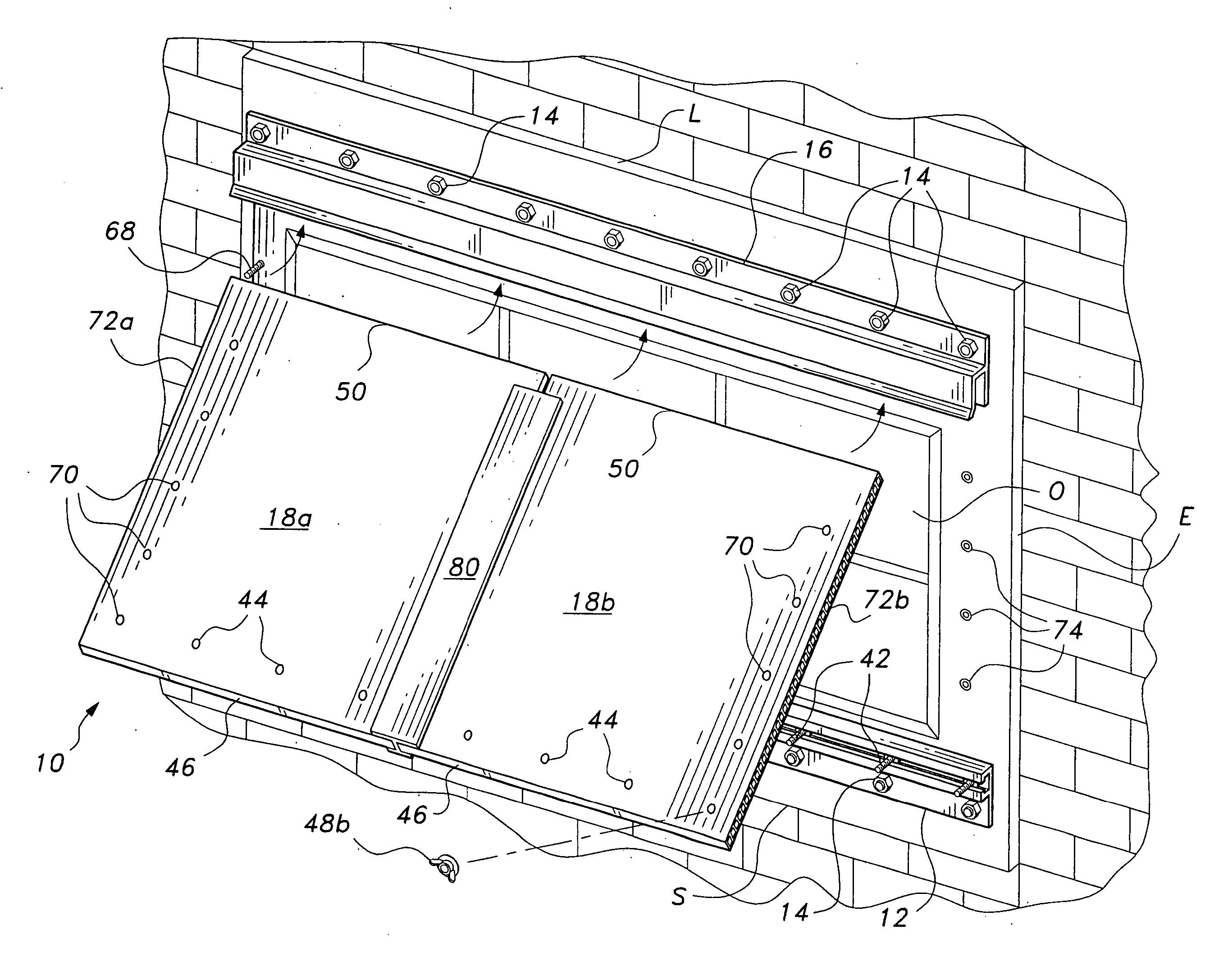
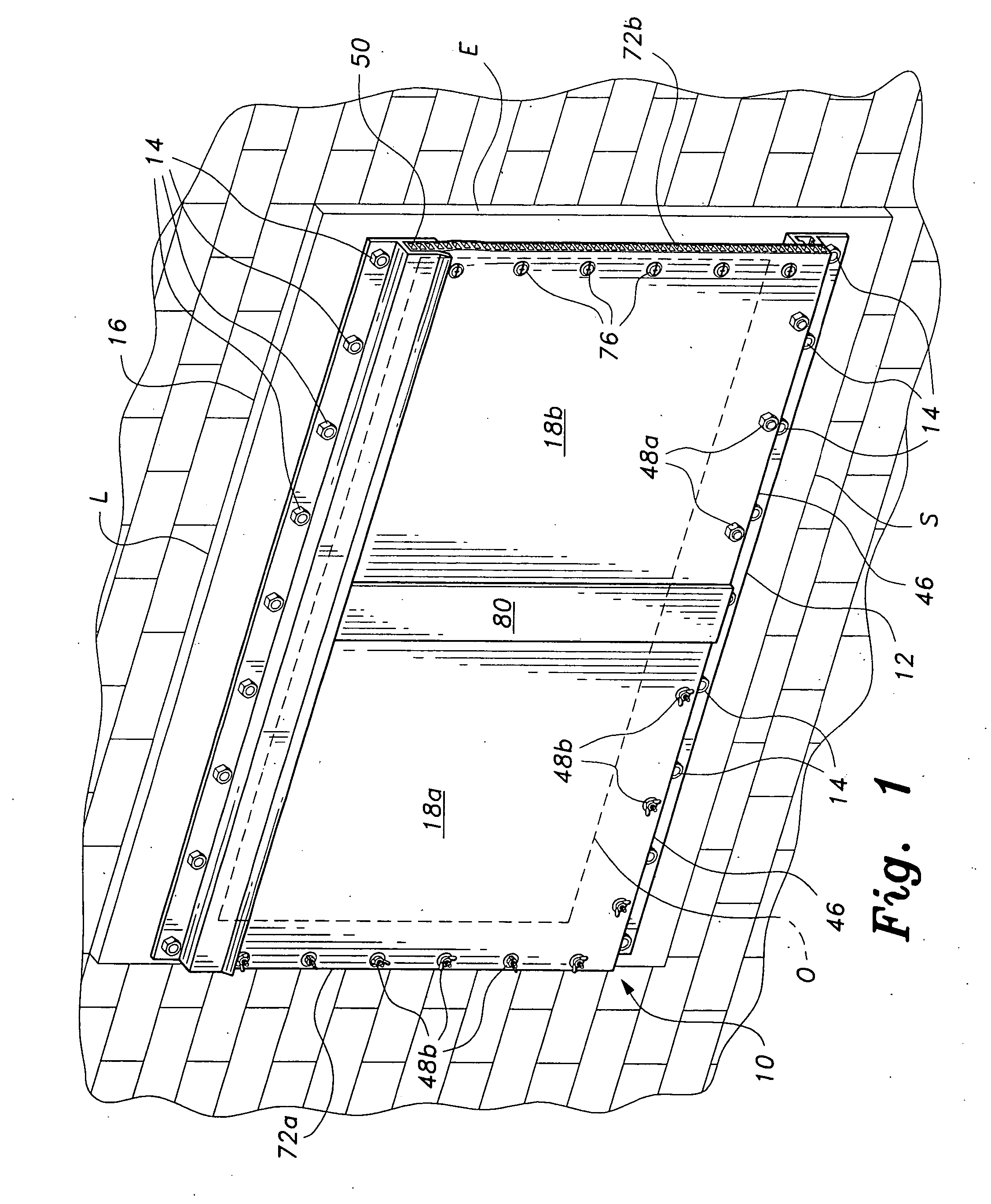
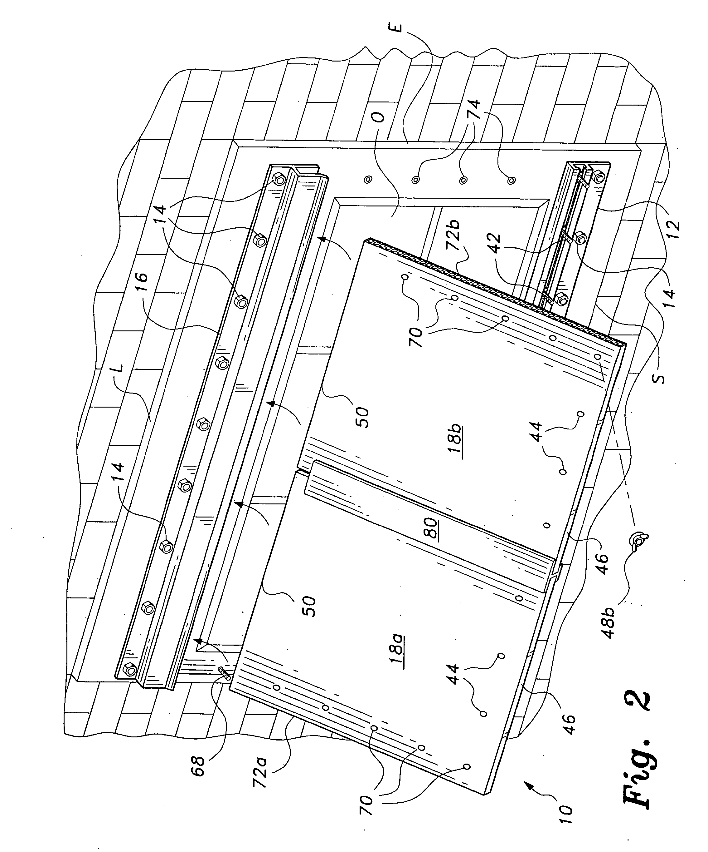
[0021] The present invention comprises various embodiments of a panel attachment system adapted particularly for use as storm window panels over door and window openings in building structures, but suitable for use in other environments as well. Upper and lower tracks or channels are permanently installed immediately above and below the structural opening, with one or more protective panels removably secured to the tracks to protect the door or window opening.

[0022]FIG. 1 of the drawings illustrates an exemplary installation of the panel attachment system, designated generally as system or panel installation assembly 10. A continuous, generally horizontal lower track 12 is permanently secured to the sill S or lower trim board of the structural opening O by a series of fasteners 14, e.g., lag bolts, threaded studs and nuts, wood screws, etc. A continuous, generally horizontal upper track 16 is permanently secured to the upper lintel L or trim board of the opening substantially paral...


PUM


Abstract

The panel attachment system includes opposite upper and lower tracks attached to the edges of an opening in a building structure, and one or more panels that secure removably to the tracks to protect the opening from extreme weather, such as hurricane force winds. The upper track has a generally “h” shaped cross section and secures the upper edge of the panel therein. The lower track has a generally “F” shaped cross section, and holds the heads of a series of threaded fasteners in the channel of the track. The threaded shanks of the fasteners protrude outwardly normal to the building structure, pass through holes formed in the lower edge of the panel, and are secured by corresponding nuts. Two or more panels may be joined to cover a wider opening. The panels may be formed of corrugated plastic material.

Description

REFERENCE TO RELATED PATENT APPLICATION [0001] This application is a continuation in part of U.S. patent application Ser. No. 11 / 254,734 filed on Oct. 21, 2005, which is hereby incorporated by reference in its entirety.BACKGROUND OF THE INVENTION [0002] 1. Field of the Invention [0003] The present invention relates generally to panel structures for covering exterior building openings (windows, doors, etc.) for protection from inclement weather, and particularly to a panel attachment system for the removable attachment of protective panels over building openings, e.g., in the manner of storm windows and the like. [0004] 2. Description of the Related Art [0005] High winds and severe weather can occur in many parts of the country during certain seasons of the year. Such conditions can be sufficiently prevalent to cause governing bodies to create standards for wind and storm protection in such areas. Examples of the above are found in the Florida State Building Code, which refers back t...

Claims


Application Information

Patent Timeline
Patent Type & Authority Applications(United States)
IPC IPC(8): E06B3/30E04G23/00
CPCE06B9/02E06B2009/005
Inventor MUNCH, JAMES A.
Owner MUNCH JAMES A
Why Eureka
Try Eureka