Particle adsorption chamber, sampling apparatus having a particle adsorption chamber, and sampling method using the same

a particle adsorption chamber and sampling apparatus technology, applied in the field of sampling methods and apparatus, can solve the problems of deformation, conventional particle counters do not provide a determination of the composition, shape, or cause of particles in the air, and achieve the effect of high degree of reliability

Inactive Publication Date: 2007-05-17
SAMSUNG ELECTRONICS CO LTD
View PDF10 Cites 10 Cited by
  • Summary
  • Abstract
  • Description
  • Claims
  • Application Information

AI Technical Summary

Benefits of technology

[0011] Objects of the present invention are to provide a device, an apparatus and a method by which the source or cause of particles in a manufacturing environment or the like can be determined with a high degree of reliability.
[0012] According to one aspect of the present invention, a particle adsorption device includes a chamber, an adsorption plate, a support disposed inside the chamber and configured to support the adsorption plate, and at least one porous plate disposed in an air flow path within the chamber. The chamber has an inlet and an outlet through which air can pass into and out of the chamber along the air flow path. A surface of the adsorption plate is exposed to air entering the chamber through the inlet. Thus, a surface of the adsorption plate will adsorb the air and thereby trap particles contained in the air on the surface. Pores of the at least one porous plate are arranged to stabilize air introduced into the chamber through the inlet at a given rate.

Problems solved by technology

Otherwise, particles will contaminate the semiconductor wafer and cause defects to occur.
That is, conventional particle counters do not provide a determination of the composition, shape, or cause of particles in the air.

Method used


Image

  • Particle adsorption chamber, sampling apparatus having a particle adsorption chamber, and sampling method using the same
  • Particle adsorption chamber, sampling apparatus having a particle adsorption chamber, and sampling method using the same
  • Particle adsorption chamber, sampling apparatus having a particle adsorption chamber, and sampling method using the same

Examples


first embodiment

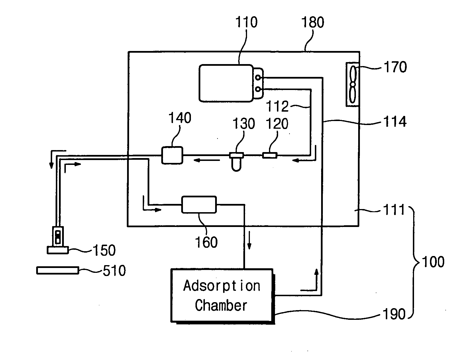
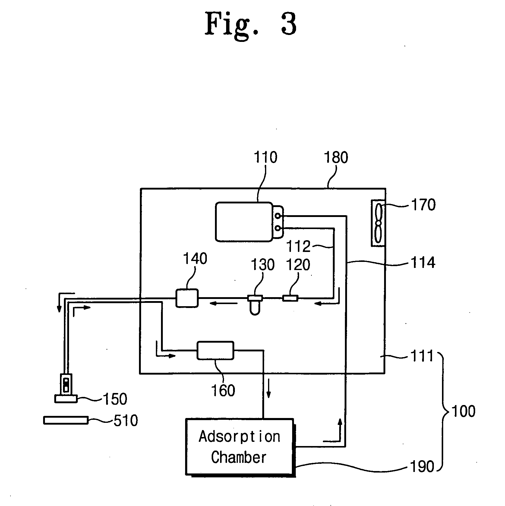
[0042] Referring to FIG. 3, a particle sampling apparatus 100 includes a particle counter 111 and an adsorption device 190 coupled to the particle counter 111. The particle counter 111 determines the sizes of particles entrained in a sample of air and counts the number of particles of each size, and the adsorption device 190 is used to determine the shape, composition, and source of the particles.

[0043] The particle counter 111 includes a pump 110 having an exhaust side at which pressure is created and an intake side at which a vacuum is created, a flow control valve 120, a first filter 130 and a second filter 140 disposed in-line with the pump 110 at the exhaust side of the pump 110, a probe 150 connected to both the exhaust side and the intake side of the pump 110, and a particle detector 160 disposed in-line with the pump 110 at the intake side of the pump 110. The pump 110 is a GAST pump, for example. The pump 110 is disposed inside a housing 180. An exhaust fan 170 is mounted t...

third embodiment

[0065] a sampling apparatus 300 according to the present invention will now be described with reference to FIG. 13. A pump 310, e.g., a GAST pump, has an exhaust side, and an intake side. An exhaust line 312 and a vacuum line 314 extend from and lead to the intake and exhaust sides of the pump 310, respectively. A probe 340 is connected to respective ends of these lines 312 and 314. The probe 340 blows air onto an object 530 (or into a manufacturing environment) and sucks air from the object 530 (or environment).

[0066] A filter 372 (referred to hereinafter as the second filter) for filtering air is installed in the exhaust line 312. A first flow directional control valve 350, an adsorption device 330, and a second flow directional control valve 370 are disposed in series in the vacuum line 314. The first flow directional control valve 350 is connected to a filter 352 (referred to hereinafter as the first filter).

[0067] The vacuum line 314 is divided at the second flow directional c...


PUM

PropertyMeasurementUnit
diameteraaaaaaaaaa
diameteraaaaaaaaaa
diameteraaaaaaaaaa

Abstract

A particle adsorption device includes a chamber having an inlet and an outlet by which air can pass through the chamber, a support for supporting an adsorbent plate in the chamber, and at least one porous plate disposed in the chamber to control the air flow through the chamber and over a surface of the adsorbent plate. A sampling apparatus includes a particle counter which has a detector that is operative to count particles of a certain size contained in the air, the particle adsorption device, and a probe by which a sample of air is sequentially or selectively fed to the particle adsorption device and the particle counter. Thus, in a method for use in monitoring a manufacturing environment for potential contamination, particles of a certain size in the air can be counted, and particles in the air can be collected on the surface of the adsorbent plate. The collected particles can be analyzed to determine their shape and composition. Te source of the particles can be traced from data produced using the sampling apparatus.

Description

BACKGROUND OF THE INVENTION [0001] 1. Field of the Invention [0002] The present invention relates to a sampling method of and apparatus for analyzing an environment for its particle content. More particularly, the present invention relates to methods of and apparatus for detecting particles as potential contaminants in an environment in which a certain level of cleanness is to be maintained, such as in a clean room of a semiconductor device manufacturing facility. [0003] 2. Description of the Related Art [0004] A semiconductor device is an extremely elaborate device fabricated by repeatedly performing a plurality of processes including photolithography, diffusion, etching, and deposition processes on a semiconductor wafer. These processes must be carried out precisely, i.e., under strict process conditions, and in an environment having a high level of cleanness. Otherwise, particles will contaminate the semiconductor wafer and cause defects to occur. [0005] A surface particle counte...

Claims


Application Information

Patent Timeline
Patent Type & Authority Applications(United States)
IPC IPC(8): G01N19/10G01N1/22
CPCG01N15/0272H01L21/02
Inventor KIM, DONG-HYUNYANG, BOK-SEOKCHO, DO-HYUNCHOI, HWAN-KINA, JUNG-HEERYU, GUNG-HANG
Owner SAMSUNG ELECTRONICS CO LTD
Why Eureka
Try Eureka