Water-Cooling Head and Method for making the same

Inactive Publication Date: 2007-05-17
COOLER MASTER CO LTD
View PDF8 Cites 14 Cited by
  • Summary
  • Abstract
  • Description
  • Claims
  • Application Information

AI Technical Summary

Benefits of technology

[0009] In view of the above drawbacks, the object of the present invention is to provide a water-cooling head and a method for making the same. Fine flowing paths formed by irregularly stacking heat-conducting particles can disturb the flow of the cooling liquid, thereby to substantially increase the staying time

Problems solved by technology

Fine flowing paths formed by irregularly stacking heat-conducting particles can disturb the flow of the cooling

Method used


Image

  • Water-Cooling Head and Method for making the same
  • Water-Cooling Head and Method for making the same
  • Water-Cooling Head and Method for making the same

Examples


Example

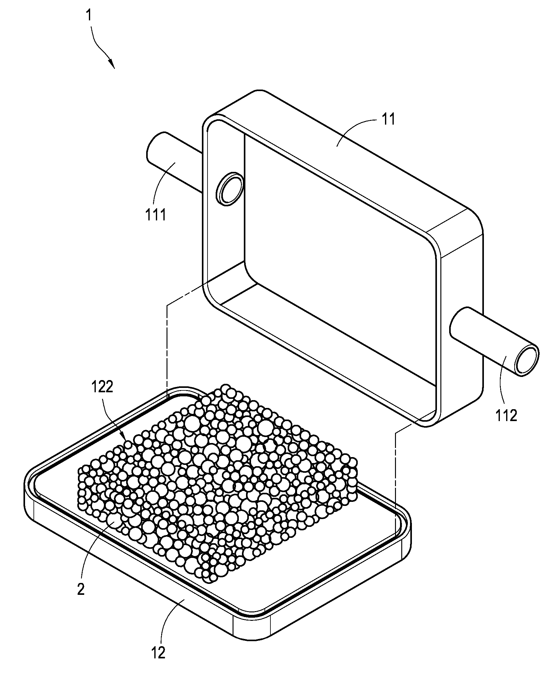
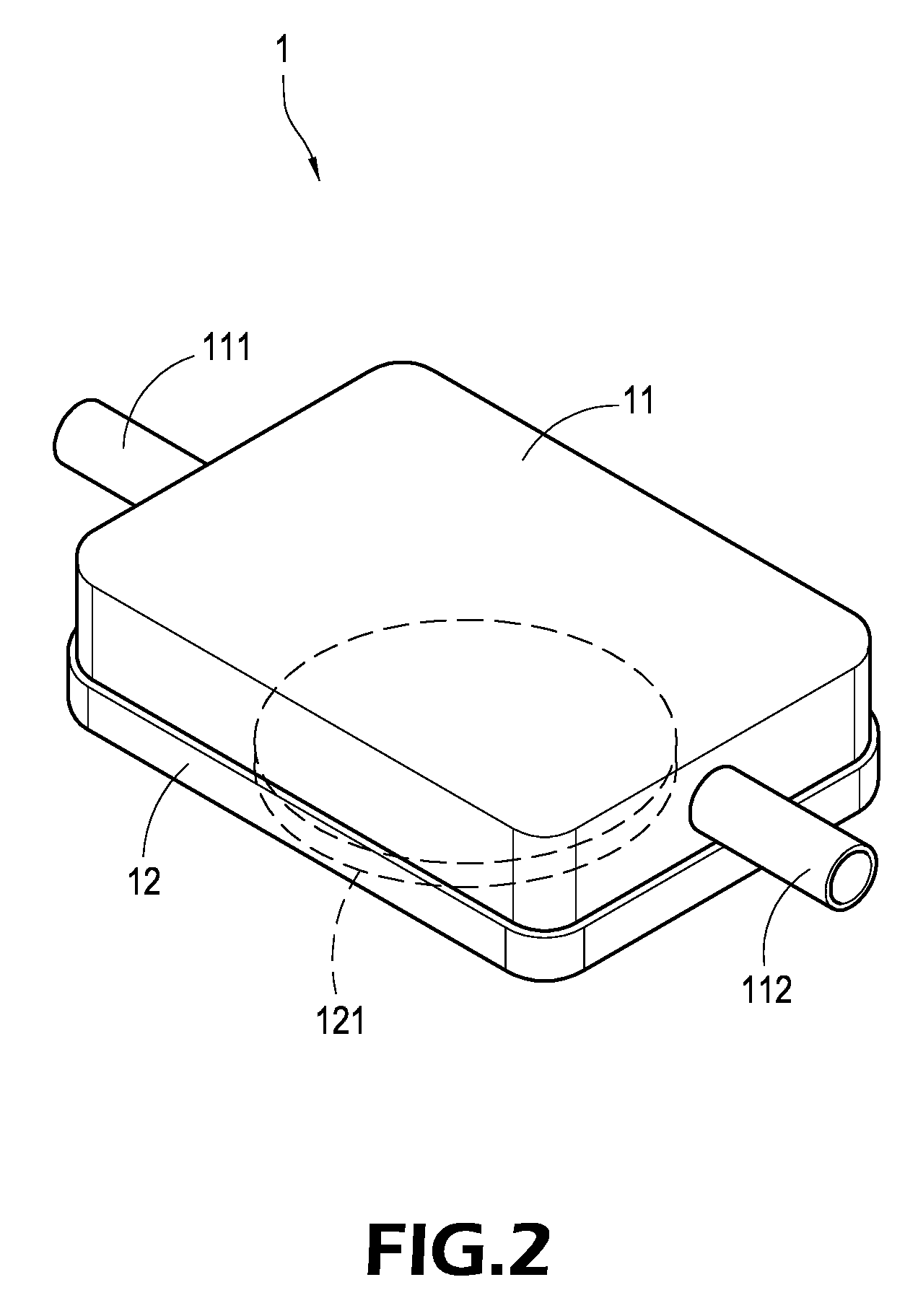
[0022] With reference to FIG. 2, it can be seen that, the water-cooling head 1 of the present invention is formed into a hollow sealed box by a first cover 11 and a second cover 12. The profile of the water-cooling head 1 can be suitably changed according to different demands. The first cover 11 and the second cover 12 of the present embodiment can be formed into a rectangular body (but not limited thereto) and made of suitable materials such as metal or ceramic. The first cover 11 and the second cover 12 are connected by means of welding, riveting or binding. In addition, an intake pipe 111 and a drainpipe 112 extend outwardly (also upwardly) from the surfaces of left and right sides of the first cover 11, respectively, thereby to provide the cooling liquid with pipes for entering and draining from the water-cooling head 1. Further, the bottom surface of the second cover 12 is provided with a contacting surface 121 thereon for contacting with a heat-generating source (not shown).

[...


PUM


Abstract

A water-cooling head and a method for making the same. A first cover and a second cover form a water-cooling head. An intake pipe and a drainpipe extend from both ends of the first cover. A plurality of heat-conducting particles is fixedly provided inside of the second cover and irregularly stacks to form a flowing path microstructure. The outside of the second cover has a contacting surface for absorbing the heat generated by the heat source and conducting the heat to the heat-conducting particles. When the cooling liquid enters the water-cooling head via the intake pipe, the flowing path microstructure disturbs the flow of the cooling liquid to prolong the staying time of the cooling liquid within the water-cooling head. In this way, the cooling liquid can be sufficiently heat-exchanged with the heat-conducting particles and then drains out from the drainpipe.

Description

BACKGROUND OF THE INVENTION [0001] 1. Field of the Invention [0002] The present invention relates to a water-cooling heat-dissipating structure and a method for making the same, and in particular to a water-cooling head suitable for electronic elements and a method for making the same. [0003] 2. Description of Prior Art [0004] The operation of any electrical apparatus will inevitably generate excessive heat due to the low efficiency and friction. Especially, the products made by modern technological industries tend to be developed with increasing precision. For example, integrated circuits or personal electronic products are gradually miniaturized in size but the heat generated by those products is increasing. Especially, since the arithmetic efficiency of the computer improves continuously, the total heat generated by the computer itself increases accordingly. Further, the heat-generating source in the computer is not limited to CPU only, other high-speed devices such as chip model...

Claims


Application Information

Patent Timeline
IPC IPC(8): H05K7/20
CPCH01L23/473H01L2924/0002H01L2924/00
Inventor PENG, YU-HUANG
Owner COOLER MASTER CO LTD
Why Eureka
Try Eureka