Ultraviolet sterilizing box structure

a box structure and ultraviolet light technology, applied in the direction of disinfection, specific water treatment objectives, chemistry apparatus and processes, etc., can solve the problems reducing utility, and achieve the effects of increasing system flow resistance, reducing utility, and increasing the utility of invention

Active Publication Date: 2022-05-24
HERGY INT CORP
View PDF6 Cites 0 Cited by
  • Summary
  • Abstract
  • Description
  • Claims
  • Application Information

AI Technical Summary

Benefits of technology

[0007]In comparison with the conventional structure, the UV sterilizing box of the invention arranges the inlet and the outlet at different sides of the box body in a perpendicular manner. Besides, the box body has a round chamber and an inner wall of the round chamber is formed with an arc-shaped guiding channel. Thus, the fluid flowing into the round chamber is guided by the arc-shaped guiding channel and slowly and spirally flows toward the inside of the round chamber under the principle of inertia to compress the water in the round chamber. Further, the compressed fluid is accelerated to flow out of the outlet at the other side of the box body. Accordingly, the staying time of the fluid in the box body is increased to avoid the fluid being last in first out. The fluid is uniformly and sufficiently irradiated by UV rays of the UV LED to accomplish sterilization and the utility of the invention is increased. Also, the fluid in the UV sterilizing box of the invention flows into the chamber instead of a thin and long flow channel. The conventional sterilizing box with a thin and long flow channel may increase the system flow resistance and decrease the utility. Comparing to the conventional sterilizing box, the flow-out rate is lower in this invention. Thus, the requirement of structural force is decreased and the utility in use is increased in this invention.

Problems solved by technology

The conventional sterilizing box with a thin and long flow channel may increase the system flow resistance and decrease the utility.

Method used


Image

  • Ultraviolet sterilizing box structure
  • Ultraviolet sterilizing box structure
  • Ultraviolet sterilizing box structure

Examples


Embodiment Construction

[0013]To further disclose the features and technical contents of the invention, please refer to the following description and the drawings. However, the drawings are used for reference and description only, not for limitation to the invention.

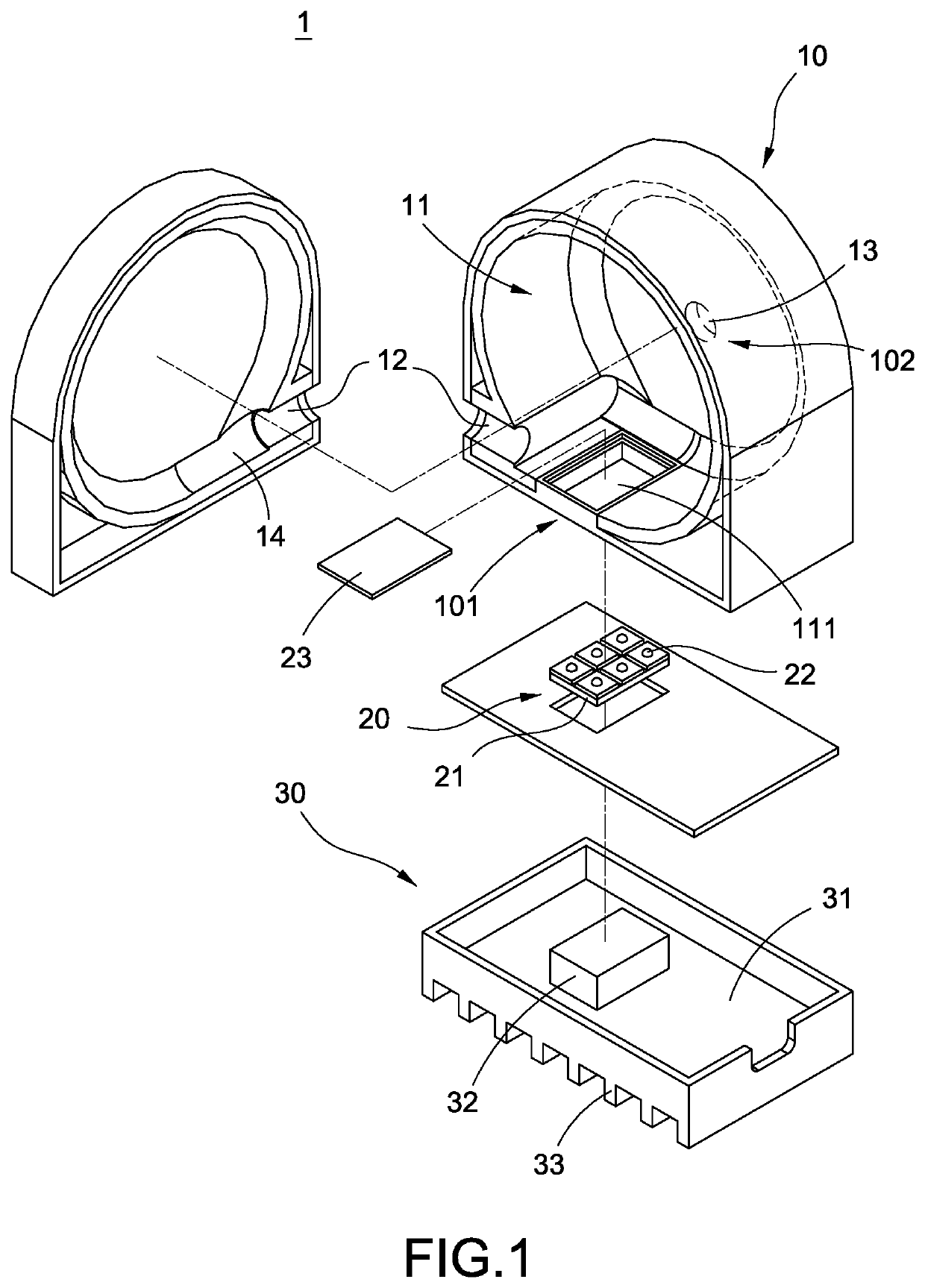
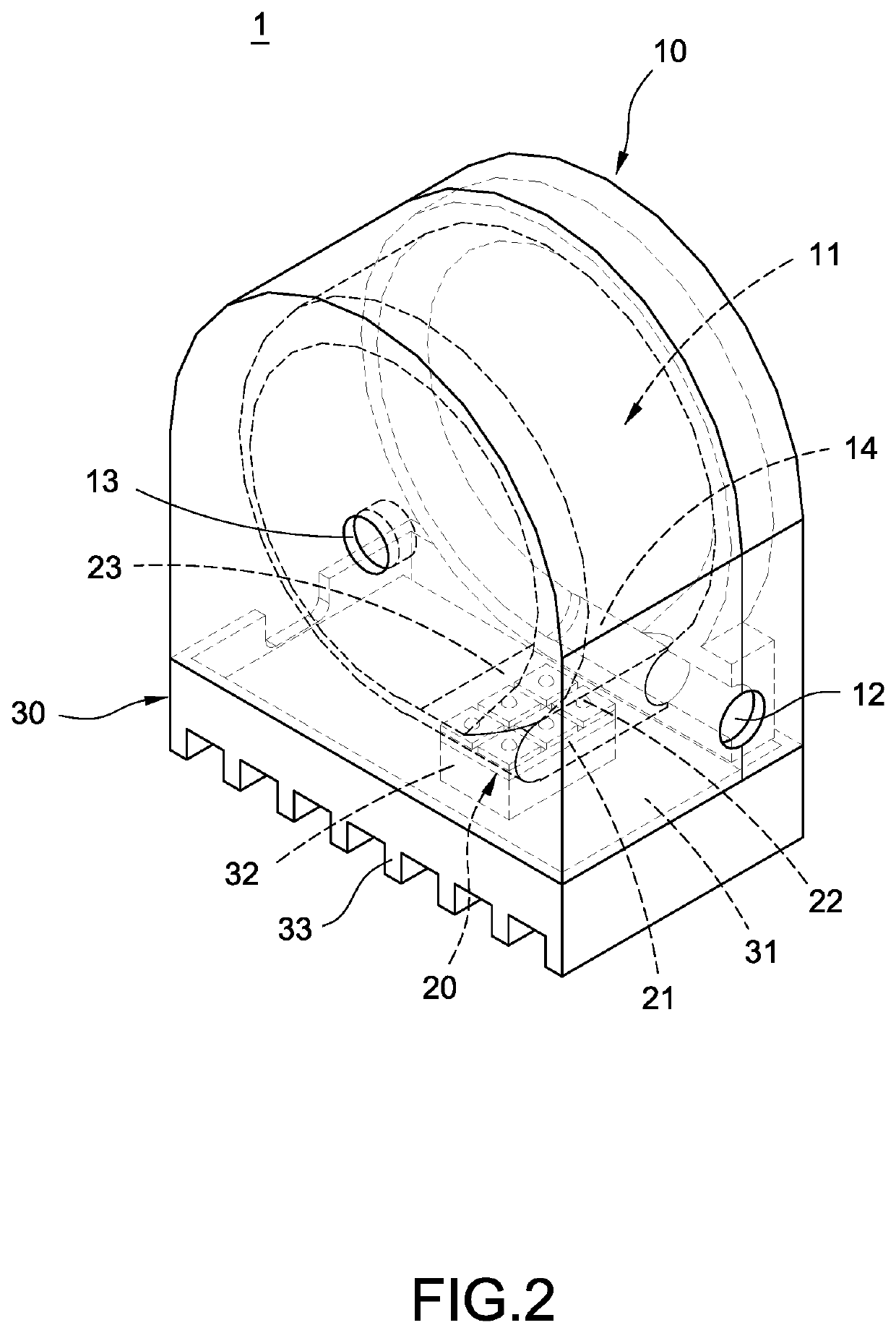
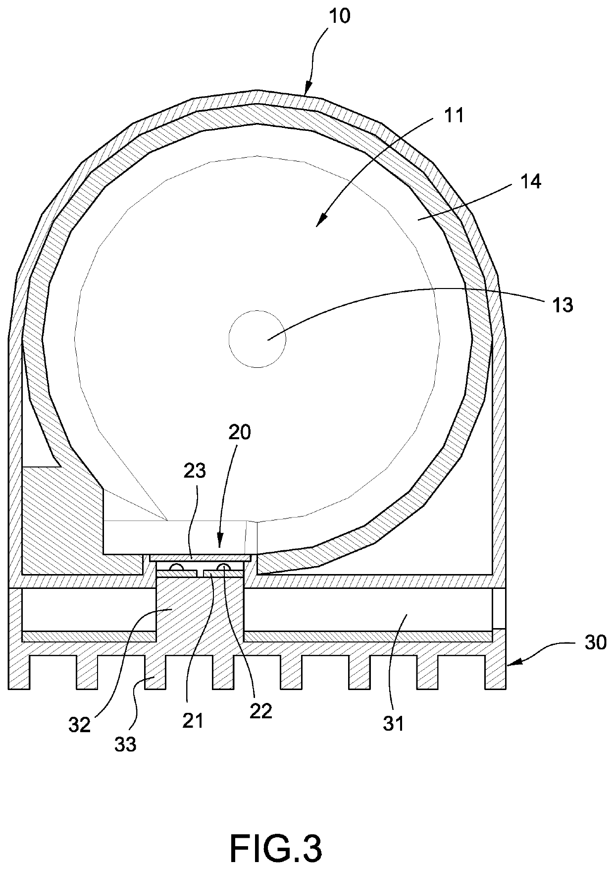
[0014]Please refer to FIGS. 1-3, which are an exploded view, a perspective schematic view and a cross-sectional view of the UV sterilizing box structure of the invention. The invention is an ultraviolet (UV) sterilizing box structure, which includes a box body 10 and a UV light module 20 connected with the box body 10. UV rays emitted by the UV light module 20 irradiate the fluid in the box body 10 to accomplish the effect of sterilization to the fluid in the box body 10. The detailed description of the UV sterilizing box structure is described as below.

[0015]The box body 10 has a round chamber 11, an inlet 12 and an outlet 13. Both the inlet 12 and the outlet 13 connect (or communicate) with the round chamber 11. An inner wall of the round cha...


PUM

PropertyMeasurementUnit
shapeaaaaaaaaaa
cylindrical shapeaaaaaaaaaa
permeableaaaaaaaaaa

Abstract

The invention is a UV sterilizing box structure. A box body has a round chamber, an inlet, and an outlet. The round chamber is formed with an arc-shaped guiding channel. A UV light module is disposed on a side of the box body. An external fluid enters the round chamber via the inlet and spirally flows through an inside of the round chamber along the arc-shaped guiding channel so as to make the fluid in the box body generate a flow with a specific direction and stay for enough time to be sufficiently irradiated by UV rays. Thereby, a better effect of sterilization may be obtained.

Description

BACKGROUND OF THE INVENTIONTechnical Field[0001]The invention relates to a UV sterilizing equipment, particularly relates to a UV sterilizing box structure.Related Art[0002]Currently, the devices with ultraviolet (UV) lamps (such as a UV light tube or LED) for sterilizing fluid such as water or air are already in the market. A UV lamp is arranged inside or outside a box and a single flow channel is used to have fluid being irradiated by UV rays. Thereby sterilization can be accomplished by irradiating the fluid with UV rays.[0003]In a conventional sterilizing box structure, the flow channel is lengthened to prolong the irradiating time. However, the volume is also increased. Also, the flow channel is flattened to decrease the irradiating distance for better effect of sterilization. However, the flow resistance is increased and the flowrate is reduced.[0004]In view of this, the inventors have devoted themselves to the above-mentioned prior art, researched intensively and cooperated w...

Claims


Application Information

Patent Timeline
Patent Type & Authority Patents(United States)
IPC IPC(8): A61L2/10A61L2/26A61L9/20C02F1/32A61L2/00
CPCA61L2/10A61L2/0047A61L2/26A61L9/20C02F1/325A61L2202/11A61L2202/122A61L2202/123A61L2209/12C02F2201/3222C02F2201/3228C02F2303/04C02F2301/026
Inventor LU, CHUN-HUNGLIN, CHIA-TECHEN, CHIH-HSIN
Owner HERGY INT CORP
Why Eureka
Try Eureka