Fluids Fluxion Method and Plant for Wastewater Treatment

a technology of wastewater treatment and fluxion method, which is applied in the direction of combustion air/fuel air treatment, machine/engine, and sedimentation settling tank, etc., can solve the problems of limited improvement of treatment efficiency, slow treatment, unstable, etc., and achieves convenient manufacture, improved wastewater treatment efficiency, and increased gas stay time

Inactive Publication Date: 2008-10-30
ECODAYS
View PDF4 Cites 4 Cited by
  • Summary
  • Abstract
  • Description
  • Claims
  • Application Information

AI Technical Summary

Benefits of technology

[0009]The present invention provides a wastewater treatment plant that can improve the wastewater treatment efficiency by providing a sludge separation unit in a reaction tank, injecting gas or air into the wastewater separation unit to increase the gas stay time in the wastewater, and decomposing and separating the sludge using a density difference by separating a gas layer from the wastewater. In addition, the present invention provides a wastewater treatment plant that is practical, economical, functional, and easy in manufacture while overcoming the problems of the prior art.

Problems solved by technology

However, a conventional treatment process has a disadvantage in that the treatment is very slow and unstable as it depends on an organic decomposition under a natural condition.
However, since most of the conventional wastewater treatment plants are designed to attach weight to only a reaction process among a variety of core processes such as a gas transmitting process, the reaction process, and a matter separation process, there is a limitation in improving the treatment efficiency.

Method used


Image

  • Fluids Fluxion Method and Plant for Wastewater Treatment
  • Fluids Fluxion Method and Plant for Wastewater Treatment
  • Fluids Fluxion Method and Plant for Wastewater Treatment

Examples


Embodiment Construction

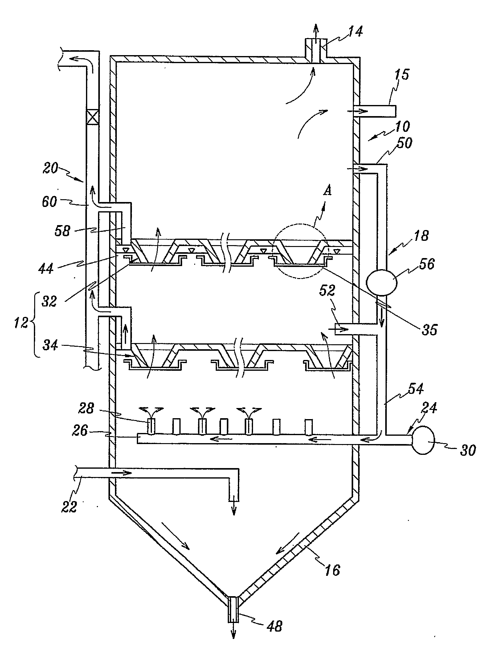
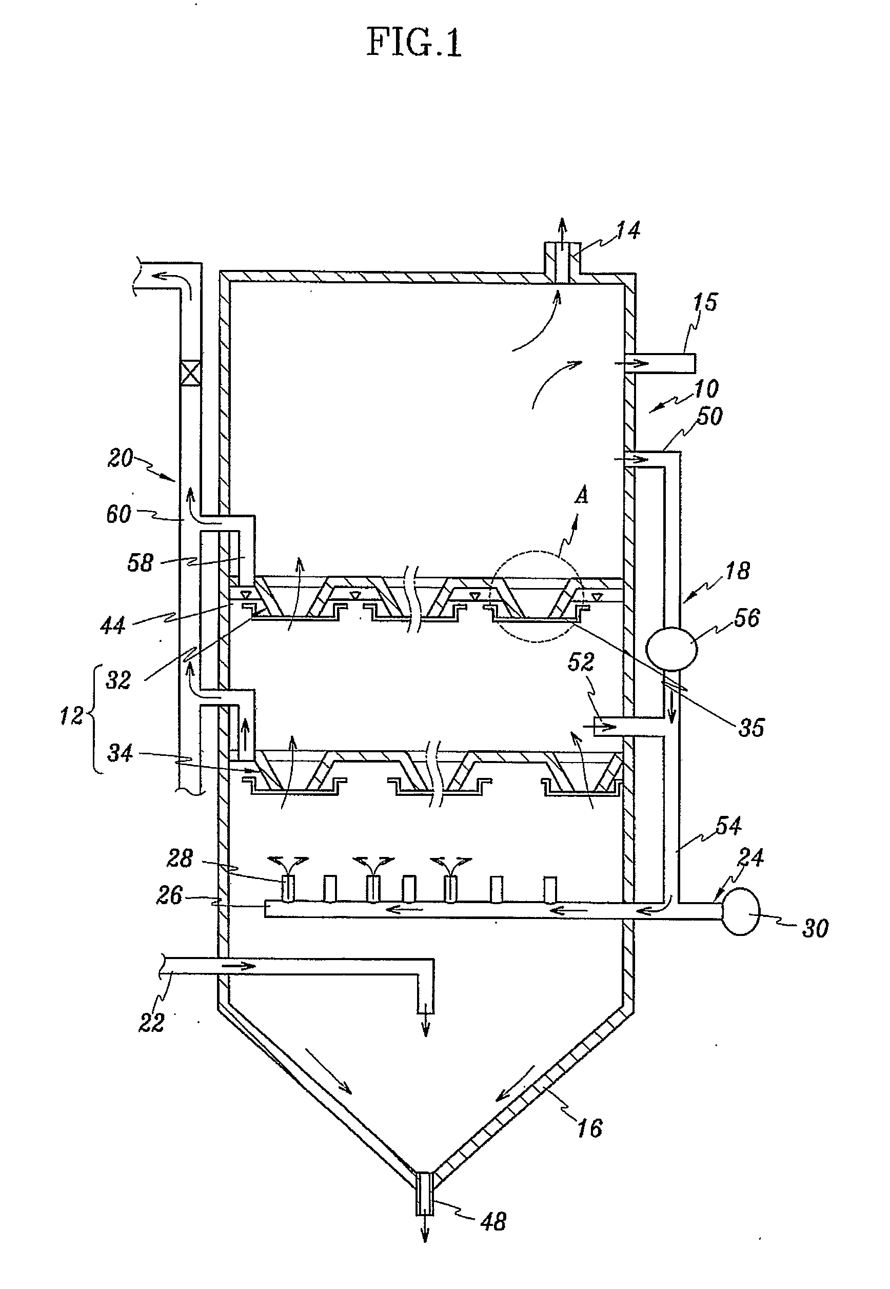
[0019]In view of the foregoing description, it is an objective of the present invention to provide a wastewater treatment plant that can stably improve the treatment efficiency of wastewater using density and viscosity properties of liquid material by mounting a unit for separating low density matters and bubbles to increase the air staying time in a reaction tank and to vary the material transmission.

[0020]It is another objective of the present invention to provide a wastewater treatment plant that can improve solubility of wastewater and air by employing a guide member.

[0021]It is still another objective of the present invention to provide a wastewater treatment plant that can circulate sludge stored in a reaction tank in a vertical direction by employing a circulating unit.

[0022]It is still another objective of the present invention to provide a wastewater treatment plant that can be operated as an anoxic tank by providing an air-exhausting unit.

[0023]It is still yet another obje...


PUM

PropertyMeasurementUnit
densityaaaaaaaaaa
solubilityaaaaaaaaaa
diameteraaaaaaaaaa

Abstract

A wastewater treatment plant includes a reaction tank connected to an wastewater supply tube and an aeration apparatus to receive wastewater therein, a sludge separation unit dividing an internal space of the reaction tank into upper and lower sections to increase an amount of dissolved oxygen by increasing an contact area of the wastewater and bubbles and to separate relatively light materials by moving low density matters existed on a surface of each section upward in turn, an air exhaust tube mounted on the reaction tank to exhaust bubbles passing through the sludge separation unit out of the reaction tank, a treated water exhaust tube mounted on the reaction tank to exhaust the wastewater that is treated by passing through the sludge separation unit, and a settling tank provided on a bottom of the reaction tank to concentrate and exhaust the settled sludge.

Description

BACKGROUND OF THE INVENTION[0001](a) Field of the Invention[0002]The present invention relates to a wastewater treatment plant, and more particularly, to a wastewater treatment plant that can improve the wastewater treatment efficiency by providing a sludge separation unit in a reaction tank, injecting gas or air into the wastewater separation unit to increase the gas stay time in the wastewater, and decomposing and separating the sludge using a density difference by separating a gas layer from the wastewater.[0003](b) Description of the Related Art[0004]Generally, a wastewater treatment is a process for converting polluted matters contained in water into stable matters through a microbiological reaction or a chemical oxidation / reduction reaction and for separating untreated residual matters.[0005]Therefore, the wastewater treatment is a technology for the water quality and stabilizing and separating organic matters and nutrition matters. To date, the wastewater treatment is perform...

Claims


Application Information

Patent Timeline
Patent Type & Authority Applications(United States)
IPC IPC(8): C02F9/00C02F9/02C02F1/52C02F1/74
CPCB01D21/0003B01D21/0036B01D21/0039B01D21/2427B01D21/2433B01D21/2488B01D21/2494C02F3/06C02F3/1247Y02A20/208Y02W10/10C02F1/74
Inventor CHOI, HONG-BOK
Owner ECODAYS
Why Eureka
Try Eureka