
Rotary steerable tool including drill string rotation measurement apparatus

a technology of rotation measurement and steerable tools, which is applied in the direction of surveying, directional drilling, and well accessories, etc., can solve the problems of miscommunication waste of valuable rig time, and sometimes more serious consequences of steering tool commands, so as to improve the accuracy and speed of downhole communication techniques, improve accuracy, and improve accuracy

Active Publication Date: 2007-05-17
SCHLUMBERGER TECH CORP +1
View PDF18 Cites 68 Cited by
  • Summary
  • Abstract
  • Description
  • Claims
  • Application Information

AI Technical Summary

Benefits of technology

[0012] Exemplary embodiments of the present invention may advantageously provide several technical advantages. For example, in one exemplary steering tool embodiment, rotation rate sensors provide for both drive shaft and housing rotation rates to be measured. Moreover, sensor arrangements according to this invention enable gravitational and tool shock / vibration acceleration components to be cancelled out. Therefore, the resulting rotation rate measurements tend to have improved accuracy. Such improved accuracy tends to advantageously improve the accuracy and speed of downhole communication techniques that rely on drill string rotation rate encoding. Exemplary embodiments in accordance with this invention also provide for substantially instantaneous rotation rate measurement, thereby enabling stick / slip conditions to be detected and accommodated.

Problems solved by technology

Rotation of the housing, if not accounted, can introduce errors into the aforementioned drill string rotation rate measurements (which measure the rotation rate of the shaft with respect to the housing), thereby potentially resulting, for example, in miscommunication of a steering tool command.
Such miscommunication requires retransmission of the command, which wastes valuable rig time.
Miscommunication of a steering command may also occasionally have more serious consequences, such as drilling the well in the wrong direction.
Furthermore, drilling conditions are often encountered in which the drill string sticks and / or slips in the borehole.
In stick / slip situations, precise measurement of the drill string rotation rate is often problematic because the rotation rate is not constant in time.
Stick / slip conditions therefore present difficulties to the timely and accurate transmission of steering tool commands downhole.

Method used


Image

  • Rotary steerable tool including drill string rotation measurement apparatus
  • Rotary steerable tool including drill string rotation measurement apparatus
  • Rotary steerable tool including drill string rotation measurement apparatus

Examples


Embodiment Construction

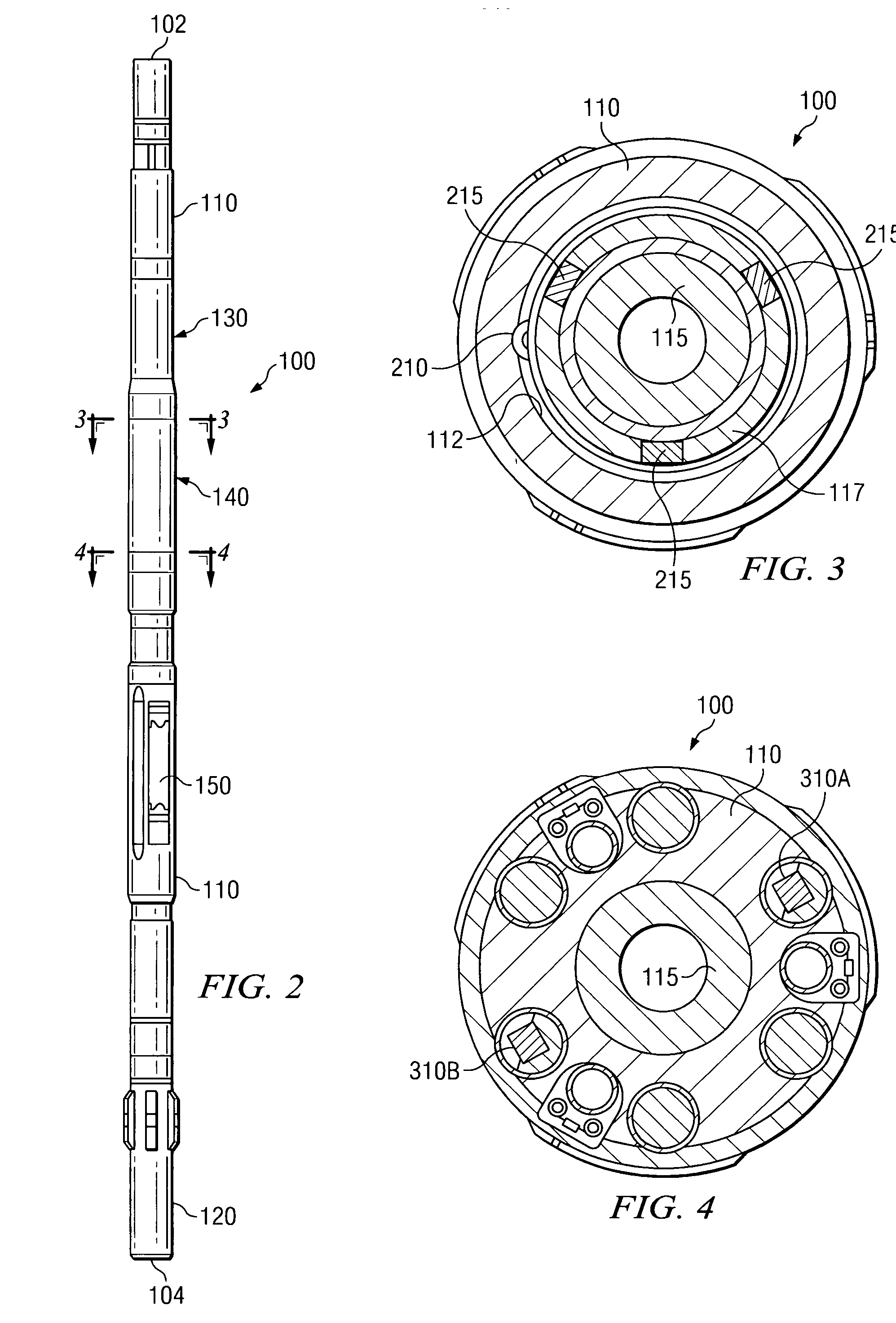
[0029] Referring to FIGS. 1 through 8, it will be understood that features or aspects of the embodiments illustrated may be shown from various views. Where such features or aspects are common to particular views, they are labeled using the same reference numeral. Thus, a feature or aspect labeled with a particular reference numeral on one view in FIGS. 1 through 8 may be described herein with respect to that reference numeral shown on other views.

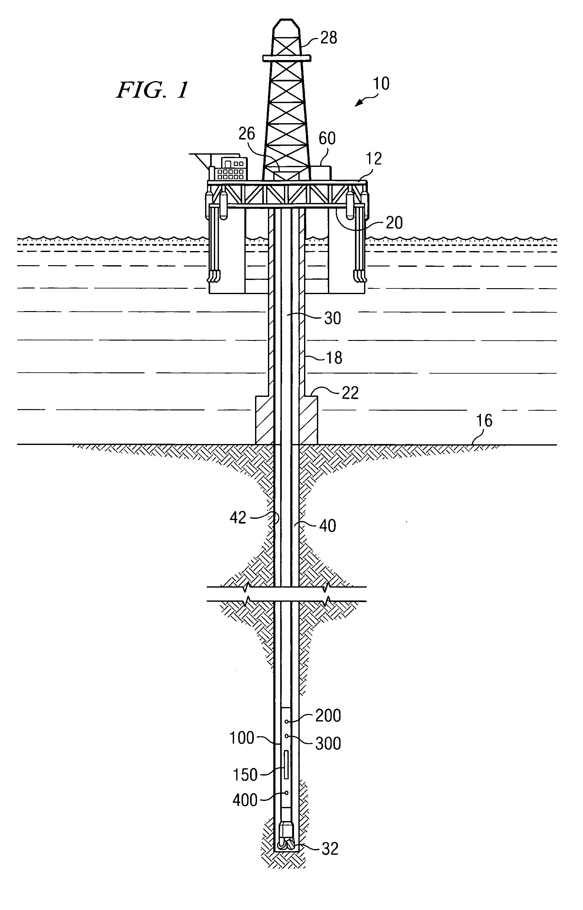
[0030]FIG. 1 illustrates a drilling rig 10 suitable for utilizing exemplary downhole tool and communication method embodiments of the present invention. In the exemplary embodiment shown on FIG. 1, a semisubmersible drilling platform 12 is positioned over an oil or gas formation (not shown) disposed below the sea floor 16. A subsea conduit 18 extends from deck 20 of platform 12 to a wellhead installation 22. The platform may include a derrick 26 and a hoisting apparatus 28 for raising and lowering the drill string 30, which, as shown, exte...


PUM


Abstract

Aspects of this invention include a downhole tool (such as a steering tool) including first and second sensor sets for measuring substantially instantaneous drill string rotation rates. Each of the sensor sets includes at least one accelerometer disposed to measure cross-axial acceleration components. Embodiments of this invention advantageously enable gravitational and tool shock / vibration acceleration components to be cancelled out, thereby improving accuracy. Moreover, exemplary embodiments of this enable stick / slip conditions to be detected and accommodated.

Description

RELATED APPLICATIONS [0001] None. FIELD OF THE INVENTION [0002] The present invention relates generally to downhole tools, for example, including three-dimensional rotary steerable tools (3DRS). More particularly, embodiments of this invention relate to a sensor arrangement configured to measure a substantially real-time rotation rate of a downhole tool. In certain exemplary embodiments, this invention relates to a rotary steerable tool including an arrangement of sensors configured to measure a drill string rotation rate. BACKGROUND OF THE INVENTION [0003] Directional control has become increasingly important in the drilling of subterranean oil and gas wells, for example, to more fully exploit hydrocarbon reservoirs. Two-dimensional and three-dimensional rotary steerable tools are used in many drilling applications to control the direction of drilling. Such steering tools commonly include a plurality of force application members (also referred to herein as blades) that may be indep...

Claims


Application Information

Patent Timeline
IPC IPC(8): E21B47/02E21B7/00
CPCE21B7/062E21B47/024E21B47/12
Inventor SUGIURA, JUNICHI
Owner SCHLUMBERGER TECH CORP
Learn More