Brake pad with wear indicator

a technology of wear indicators and brake pads, applied in the field of brake pads, can solve problems such as catastrophic danger and damage, braking is disturbed, and expensive parts are eroded

Inactive Publication Date: 2007-05-17
MCCLELLAN WILLIAM THOMAS
View PDF4 Cites 20 Cited by
  • Summary
  • Abstract
  • Description
  • Claims
  • Application Information

AI Technical Summary

Benefits of technology

[0020] It is accordingly an object of the invention to provide a brake pad with a wear indicator, which overcomes the hereinafore-mentioned disadvantages of the heretofore-known devices of this general type and which provides a simple, reliable, effective, failsafe, c

Problems solved by technology

It is in the process of using up the friction material that braking is disturbed and catastrophic danger and damage occur.
Wear-through of the brake pads can create an emergent brake failure and the resultant metal-to-metal contact can erode expensive parts.
Brake pads suffer extremes in mechanical forces and temperatures.
Thin metal noise makers (blades or springs mounted on the pads) are only mounted on front brakes and have limited use because they are not used on rear wheels, trailers, buses, large trucks, construction equipment or airplanes.
They not only suffer that inaccuracy, but lack reliability and increased maintenance, inherent to their complexities of gears, cams, followers, pins, contacts, electric wires, circuit breakers and lights.
They are especially failure prone in the hostile environment of the exposed wheel location, with high “G” loads, vibrations of the bouncin

Method used


Image

  • Brake pad with wear indicator
  • Brake pad with wear indicator
  • Brake pad with wear indicator

Examples


Embodiment Construction

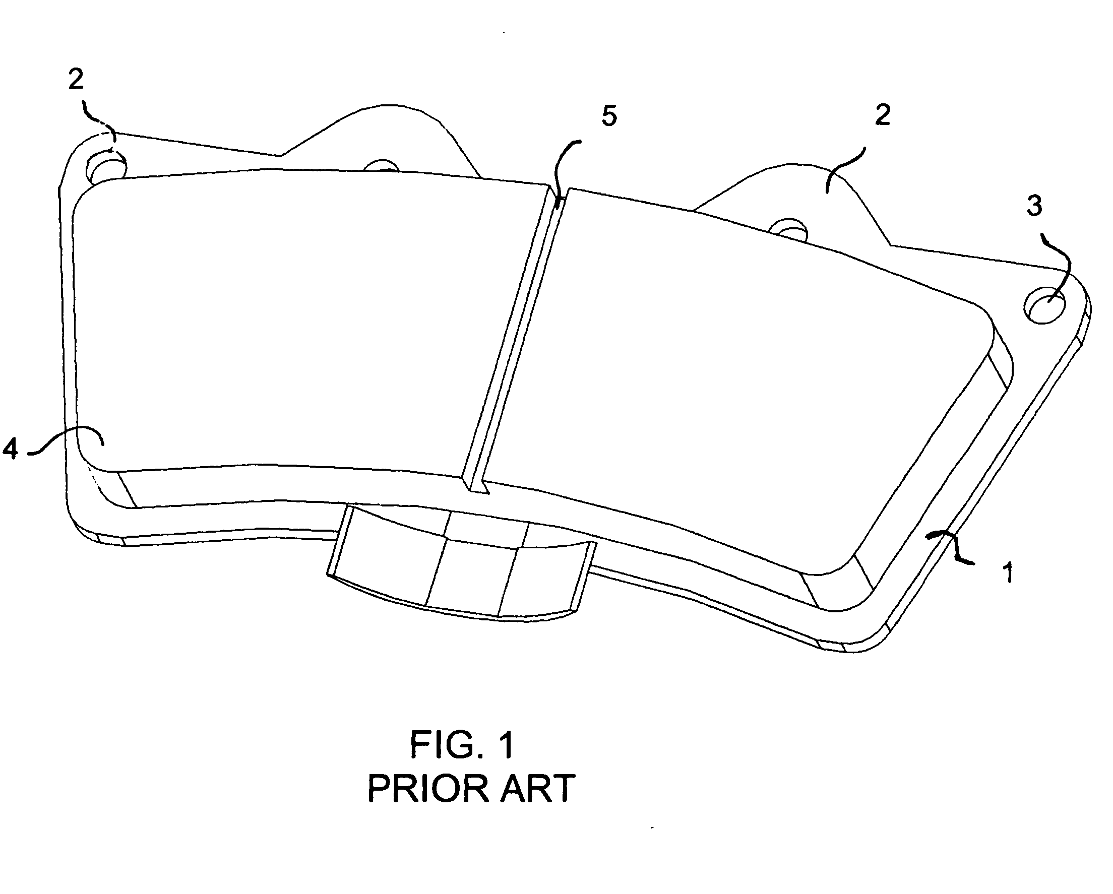
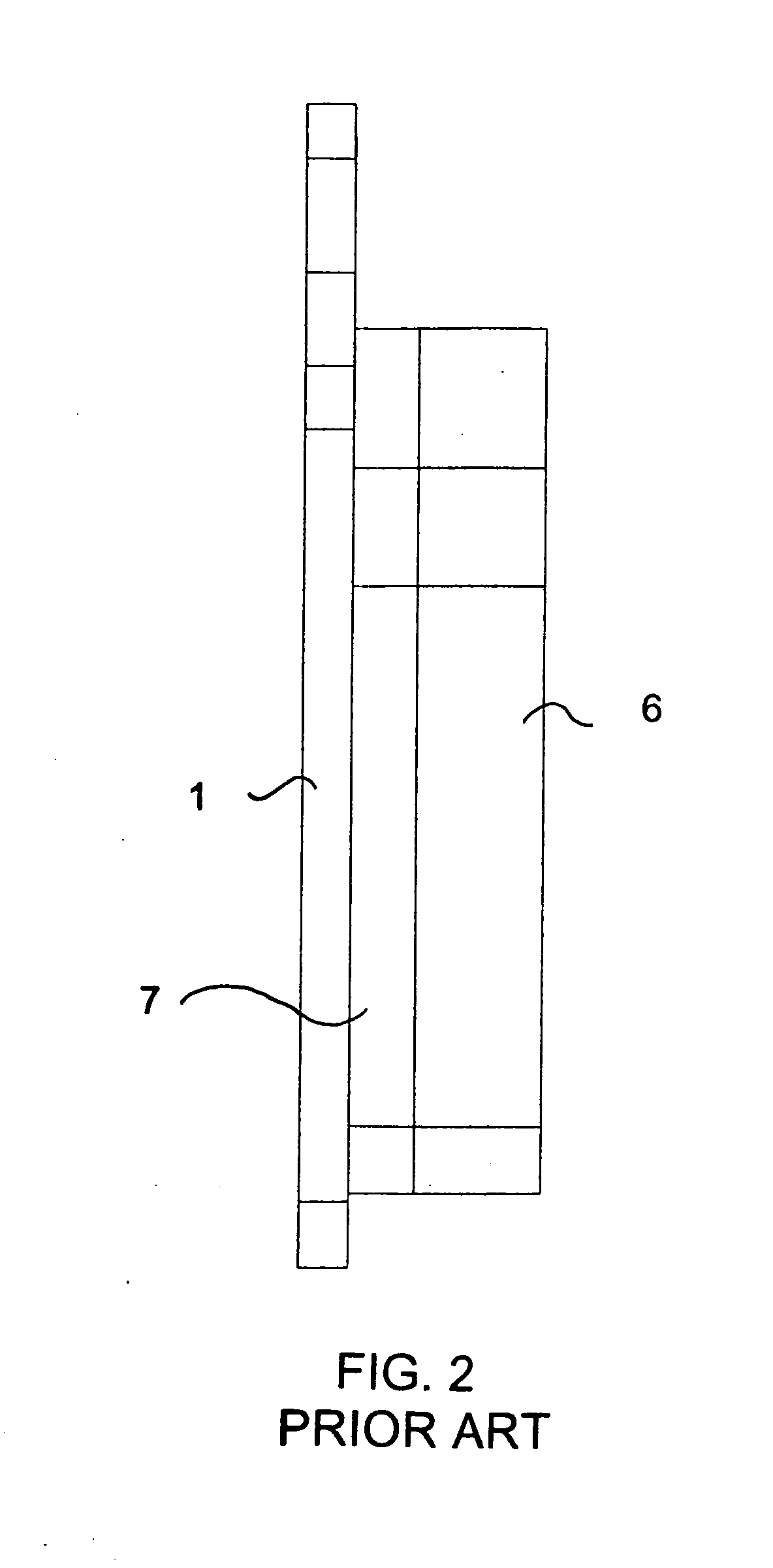
[0040] Referring now in detail to the figures of the drawing, in which the same reference numerals have been used for similar features, and first, particularly, to FIG. 1 thereof, there is seen a prior art brake pad having a backing plate 1 with lugs 2 in which mounting holes 3 are formed. A friction material layer 4 is attached to the backing plate 1 for pressing against a rotor or drum. The friction material layer 4 is formed of a strong matrix of tough aramid fibers, rock-hard, sharp-edged, friction particles and heat-resistant hardening resin, which are specially provided for an environment encountering extremes in mechanical forces and temperatures. The integrity of the layer depends on a uniform cohesiveness throughout the layer and strong attachment to the backing plate. A groove 5 is cut into the friction material layer 4 to indicate the wear level. Holes may also be formed in the friction material layer to provide the same wear level indication function. The wear at such gr...


PUM


Abstract

A brake pad includes a backing plate and a friction material layer attached to the backing plate. At least one inner layer is disposed within the friction material layer. The inner layer has a color different than the friction material layer.

Description

BACKGROUND OF THE INVENTION [0001] 1. Field of the Invention [0002] The invention relates to a brake pad with a backing plate, a friction material layer and a wear indicator. [0003] 2. Description of the Related Art [0004] All modern ground transportation, that is motorcycles, bicycles, automobiles, trucks, construction equipment and even airplanes during taxi, takeoff and landing, control deceleration by converting the vehicle's kinetic energy or mass velocity, into heat by a system of friction braking. [0005] Generally a pad and a rotor or a shoe and a drum configuration are used. The pad or shoe (made of a special friction absorbing material) is connected to the vehicle, and is pressed against a metal rotor or drum attached to the rotating axle or wheel. As the friction part is pressed against the rotating part, energy is absorbed, and the vehicle decelerates. [0006] The friction material is constructed to maximize strength, friction co-efficient and heat tolerance, but not be so...

Claims


Application Information

Patent Timeline
IPC IPC(8): F16D66/02
CPCF16D66/028F16D2069/005
Inventor MC CLELLAN, W. THOMAS
Owner MCCLELLAN WILLIAM THOMAS
Why Eureka
Try Eureka