Irrigation emitter

a technology of irrigation emitter and emitter body, which is applied in the field of drip irrigation, can solve the problems of affecting the flow rate of the emitter, the failure of the emitter to meet the failure of the assembled emitter and the tubing to reach the specified flow rate, etc., and achieves the effect of high customization and easy adaptation to different flow rates

Inactive Publication Date: 2007-05-17
MAMO SHAY +1
View PDF2 Cites 36 Cited by
  • Summary
  • Abstract
  • Description
  • Claims
  • Application Information

AI Technical Summary

Benefits of technology

[0014] The device herein disclosed and described provides for an assembled irrigation emitter that overcomes the shortcomings of previous designs of molded emitters providing filtering, pressure compensation and backflow prevention, where the labyrinth is positioned on the outside circumference of the assembled emitter where contact with malleable tubing is possible, or in contact with internal flexible seals. The disclosed device does so by providing a dripper body that is engageable with a body cover to yield an emitter having a curved sidewall adapted for easy engagement with flexible tubing during extrusion. The dripper body is adapted on one side of its center axis for engagement with the flexible tubing and on the other side with the body cover. The body cover has the labyrinth formed on a side surface that faces the dripper body, rather than on the opposite side surface that engages the sidewall of the extruded flexible tubing. The dripper cap can be formed with a variety of different labyrinths such that the flow rate of the final assembled dripper can be varied to meet the desired ultimate location for the tubing and emitters. However, placing the labyrinth on the dripper cover such that it is internal to the assembled emitter virtually eliminates potential problems from soft or malformed tubing inhibiting emitter flow by blocking or constricting labyrinth paths. The engageable dripper body has a filter formed on its input side wherein water is communicated from the conduit. The device is much smaller than the emitter body and consequently cheaper to manufacture and various configurations can be stocked to easily change the flow and filtering characteristics of the engaged emitter body during manufacture.

Problems solved by technology

However, with the global economy which has developed in the last decade, a problem has begun to occur in the industry with regard to maintaining the specified flow rates from emitters designed for internal mounting in flexible conduits.
The same problem is occurring with the components employed to assemble the emitters adapted to be engaged in the flexible plastic conduit during extrusion.
The problem on the emitters is exacerbated when the emitters themselves are assembled from various components manufactured by multiple vendors using multiple supply sources for raw material in the molding or extrusion process.
The result of this plurality of raw material suppliers in a plurality of locales, providing a plurality of different emitter components and tubing manufacturers operating in multiple venues, has gradually caused problems with the assembled emitters and tubing reaching the designed specified flow rates, backflow prevention, and pressure compensation.
Such variances from acceptable specifications caused by this plurality of venues, suppliers, and manufacturers is becoming a growing problem in the industry.
One especially vexing problem can easily occur if tubing or flexible conduit engaged to the assembled emitter is produced from raw materials that are too malleable or too easily deformed during temperature variations.
If the tubing is too soft or reacts to temperature changes, it can actually deform into or deflect into the small serpentine path of the labyrinths formed on the exterior surface on such emitters.
Deflection or deformation of the tubing sidewall to interfere with fluid flow in the labyrinth can cause widely varying flow rates from the resulting assembled tubing and emitters.
Still further, if a flexible membrane is employed within the emitter body for pressure compensation and / or anti-siphon properties, contact of the membrane with any portion of the labyrinth can cause the same problems noted as the membrane contacting the malleable tubing.
Another problem can arise with the expansion and contraction rates of the tubing being such that heat or cold causes the malleable tubing sidewall engaging the exterior of the emitter body to deform and again inhibit flow through the small passages of the external labyrinth conventionally placed on many currently employed emitters fused to the sidewall of such tubing.
Further, the emitter body itself can end up too large or too small from the different tolerances employed by the various manufacturers of the raw material or assembled body components.
This too can cause the sidewall forming the tubing to inhibit flow in the exterior formed labyrinth in some cases.

Method used


Image

  • Irrigation emitter
  • Irrigation emitter
  • Irrigation emitter

Examples


Embodiment Construction

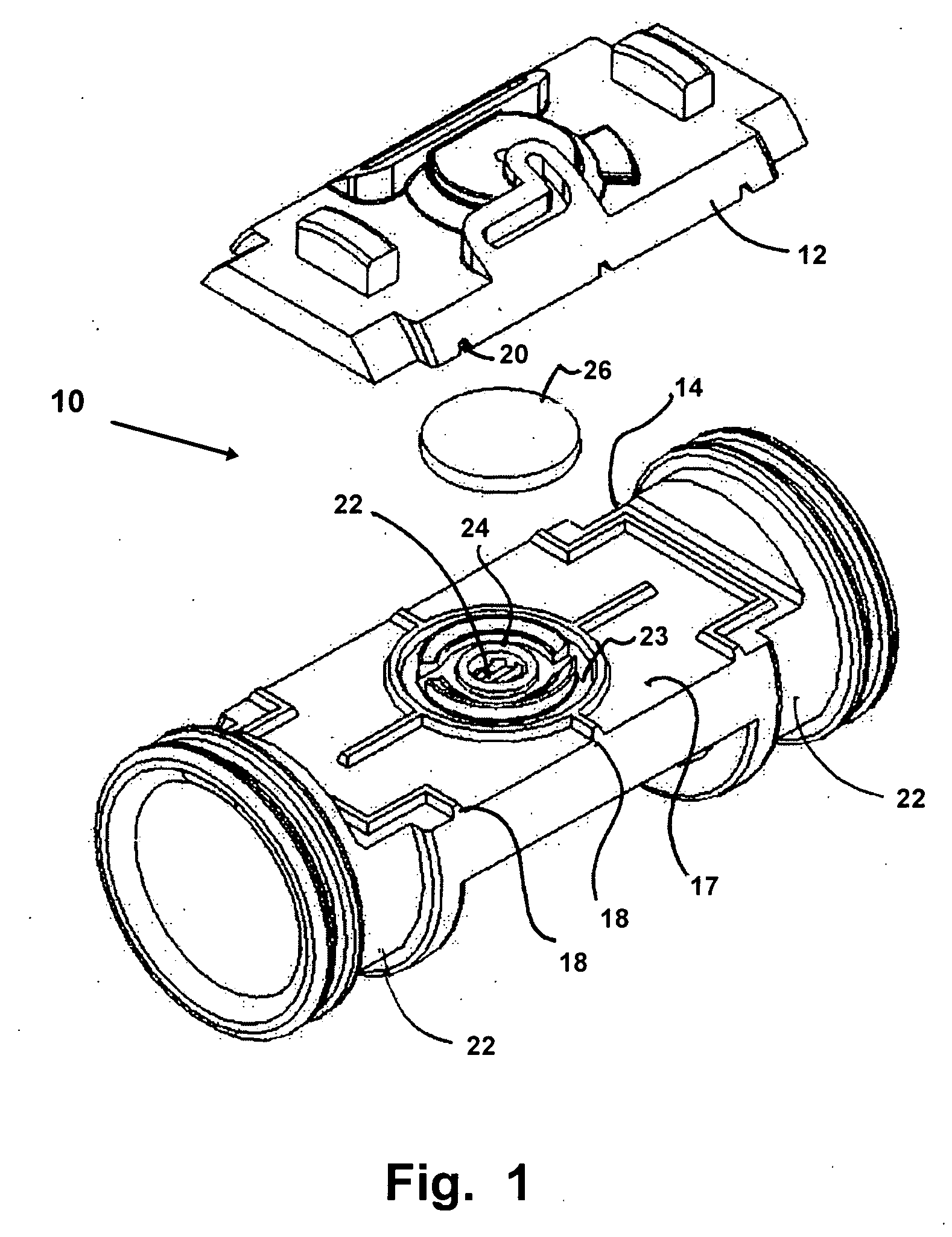
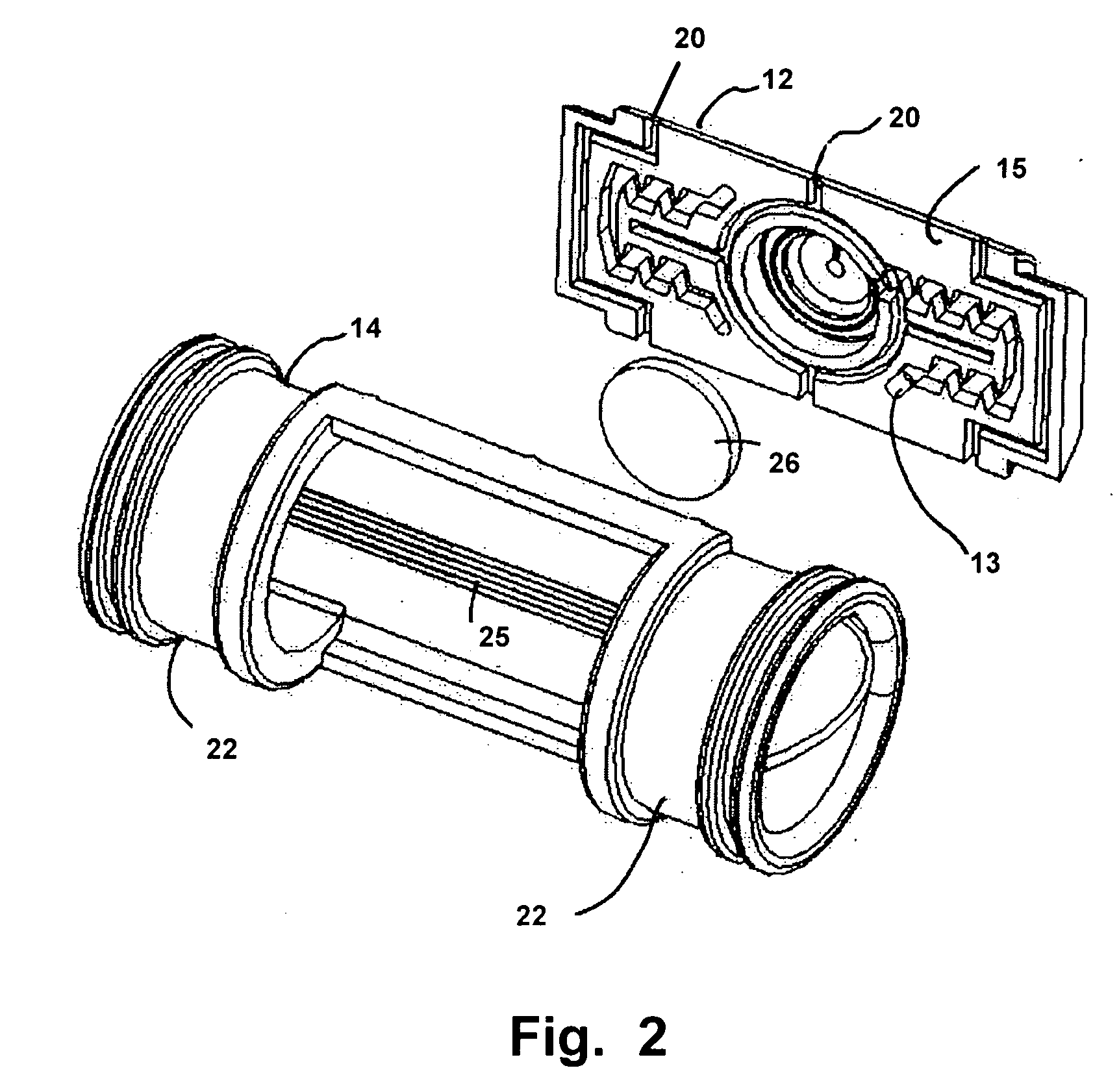
[0039] Referring now to the drawings, FIGS. 1-13 depict the various embodiments and engagements of the disclosed apparatus and device producing an assembled emitter device 10 that can be customized for flow characteristics, yet eliminate the problems inherent where many manufacturers are involved in making the raw materials and various components intended for a final tubing and emitter assembly.

[0040] The emitter device 10 features a dripper cap 12 available in a plurality of flow configurations, which is adapted for engagement to a properly configured dripper body 14. The dripper cap 12 can be manufactured in a number of configurations as a means to adjust fluid flow rates by changing dimensional characteristics of a labyrinth 13, including one or a combination of characteristics from a group of dimensional characteristics including total aggregate length of said labyrinth 13, diameter of said labyrinth 13, and number and length of individual segments ending at turns in the labyri...


PUM


Abstract

A fluid emitter adapted for engagement within a malleable conduit during extrusion of the conduit. The emitter is formed of two components and has fluid labyrinth formed in a position to eliminate contact with the malleable wall of the extrusion or conduit to thereby eliminate potential variations in flow from deformation of the wall forming the conduit caused by conduit manufacturing variances. Fluid flow characteristics of pressure and volume in fluid emitted may be adjusted by mating one of a plurality of dripper caps with varying labyrinth characteristics with a single body configuration thereby minimizing inventory requirements for manufacturers.

Description

FIELD OF THE INVENTION [0001] This application claims the benefit of U.S. Provisional Patent Application No. 60 / 736,827, filed Nov. 14, 2005. The invention herein disclosed and described relates to drip irrigation. More particularly it relates to pressure compensating and water filtering for drippers or water emitters used for irrigation which are engaged internally along lengths of water carrying malleable tubes, tapes, and conduits. The disclosed emitter features a body formed of two components which combine to form the device and to position a formed labyrinth such that it does not contact the malleable conduit in which the emitter body is engaged or the flexible membrane employed for pressure compensation and backflow prevention.BACKGROUND OF THE INVENTION [0002] Drip irrigation for many years has been a cost and water reducing method of irrigating crops and landscaping. In practice, an elongated malleable conduit in the form of a pipe, plastic tube, or inflatable tape, communic...

Claims


Application Information

Patent Timeline
Patent Type & Authority Applications(United States)
IPC IPC(8): B05B15/00
CPCA01G25/023
Inventor MAMO, SHAYHAVAZELET, DAVID
Owner MAMO SHAY
Why Eureka
Try Eureka