Method of fabrication of high temperature superconductors based on new mechanism of electron-electron interaction

a superconductors and electron-electron technology, applied in the direction of superconductors, electrical devices, semiconductors, etc., can solve the problems of not fully applicable to this range of superconductors, not fully known superconductivity theory,

Inactive Publication Date: 2007-05-17
TAVKHELIDZE AVTO
View PDF20 Cites 37 Cited by
  • Summary
  • Abstract
  • Description
  • Claims
  • Application Information

AI Technical Summary

Problems solved by technology

However, HTS' high temperatures of superconductive transition and extremely low value of order parameters (the distance at which the wave function of the Bose condensate changes its phase) indicate that the traditional theory of superconductivity known as the BCS theory [J. Bardeen, L. Cooper, J. Schrieffer “Theory of Superconductivity” Phys. Rev., 108, 1175-1204 (1957)] is not fully applicable to this range of superconductors.
Several such theories have been suggested to date but none have proven sufficient.
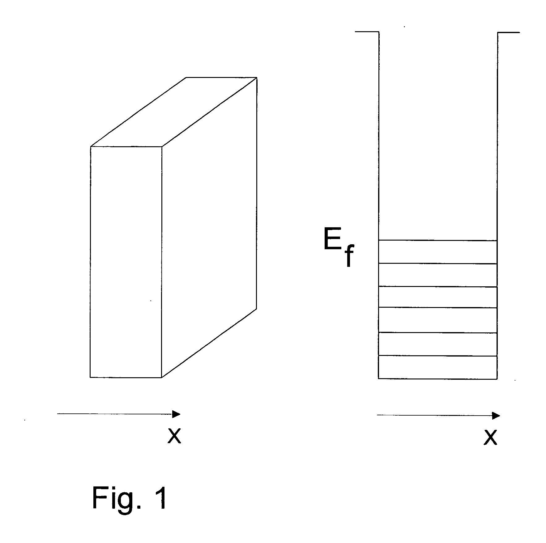
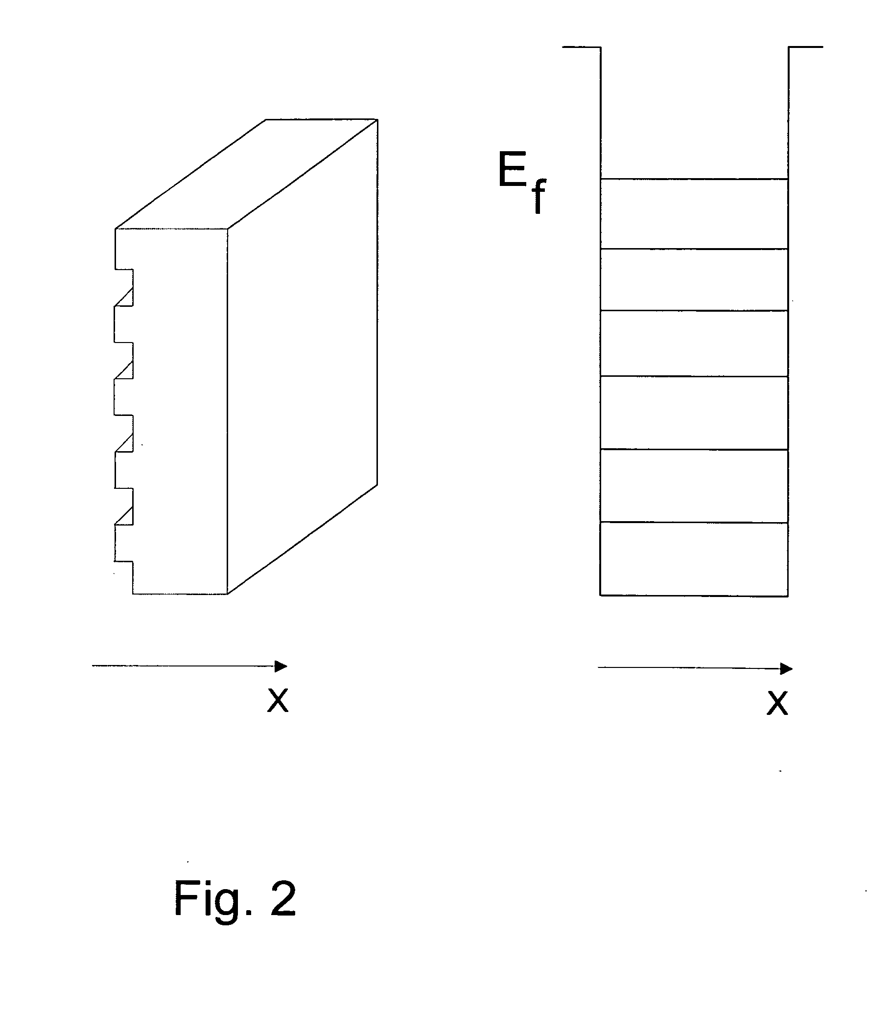
Electron waves reflected from the top and bottom of each indent interfere destructively, thereby canceling each other out and preventing reflection from the modified wall.

Method used


Image

  • Method of fabrication of high temperature superconductors based on new mechanism of electron-electron interaction
  • Method of fabrication of high temperature superconductors based on new mechanism of electron-electron interaction
  • Method of fabrication of high temperature superconductors based on new mechanism of electron-electron interaction

Examples


Embodiment Construction

[0030] Embodiments of the present invention and their technical advantages may be better understood by referring to FIGS. 3-5. [31] The mechanism proposed as responsible for the present invention is best explained by referring to FIG. 3. Referring now to FIG. 3, which shows a first MPEB and a second MPEB as the external object referred to in the earlier discussion. We now have a composite system containing two excited subsystems of electrons in SDFG. It is clear that when the two MPEBs come close to each other, previously forbidden energy levels (shown as dotted lines in FIG. 3) start to reanimate in both due to the possibility of tunneling to the neighboring MPEB. Both MPEBs will attract each other with an attractive force that increases as the distance between the MPEBs decreases. Further, it is clear that it is the electrons from the two subsystems of SDFGs that attract each other. This type of attraction can be regarded as the mechanism responsible for the creation of Cooper pai...


PUM


Abstract

The present invention is a superconducting tunnel junction comprising two thin films characterized in that the thin films have an indented surface facing each other and are separated by an insulator layer. Typically, the depth of the indents is in the range of 5 to 10 nm, the width of the indents is in the range of 50 to 200 nm, the thickness of the insulator layer is in the range of 1 to 3 nm, and the thickness of the films is less than electron mean free path of a material comprising said films, and is typically in the range of 50 to 100 nm. Preferably the films are single crystal films or amorphous films.

Description

CROSS-REFERENCE TO RELATED APPLICATIONS [0001] This application claims the benefit of U.K. Provisional Patent App. No. GB0517167.3, filed Aug. 23, 2005. This application is a Continuation-in-Part of U.S. patent application Ser. No. 10 / 991,257, filed Nov. 16, 2004, which is a Continuation-in-Part application of application Ser. No. 10 / 508,914 filed Sep. 22, 2004, now U.S. Pat. No. 7,074,498, which is a U.S. national stage application of International Application PCT / US03 / 08907, filed Mar. 24, 2003, which international application was published on Oct. 9, 2003, as International Publication WO03083177 in the English language. The International Application claims the benefit of U.S. Provisional Application No. 60 / 366,563, filed Mar. 22, 2002, U.S. Provisional Application No. 60 / 366,564, filed Mar. 22, 2002, and U.S. Provisional Application No. 60 / 373,508, filed Apr. 17, 2002. This application is also a Continuation-in-Part application of application Ser. No. 10 / 760,697 filed Jan. 19, 20...

Claims


Application Information

Patent Timeline
Patent Type & Authority Applications(United States)
IPC IPC(8): H01L39/22H01L29/06H01L29/08
CPCH01L39/223H10N60/12
Inventor TAVKHELIDZE, AVTO
Owner TAVKHELIDZE AVTO
Why Eureka
Try Eureka