Sheet processing apparatus and image forming apparatus

a technology of image forming apparatus and processing apparatus, which is applied in the directions of transportation and packaging, thin material processing, and article delivery, etc., can solve the problems of increasing cost, complicating the apparatus configuration, and insufficient alignment, and achieves high efficiency and low cost. , the effect of enhancing the alignment property

Inactive Publication Date: 2007-05-17
CANON KK
View PDF16 Cites 22 Cited by
  • Summary
  • Abstract
  • Description
  • Claims
  • Application Information

AI Technical Summary

Benefits of technology

[0016] According to the sheet processing apparatus of the present invention, sheets are divided into a sheet group made up of a plurality of sheets and then moved, and aligning and stacking are performed all at once with respect to each group to form a sheet bundle including a predetermined number of sheets on the processing tray. The temporal margin is thereby produced compared to when aligning and stacking are performing one sheet at a time, and thus is effective in realizing high speed process a

Problems solved by technology

However, the sheet processing apparatus disclosed in one of the above publications has the following problems.
Furthermore, if the sheet stack in which the sheets are superimposed in pluralities is fed to the processing tray in the state of a skew feeding, the alignment may not be sufficiently performed as correction of

Method used


Image

  • Sheet processing apparatus and image forming apparatus
  • Sheet processing apparatus and image forming apparatus
  • Sheet processing apparatus and image forming apparatus

Examples


first embodiment

Staple Sort Mode

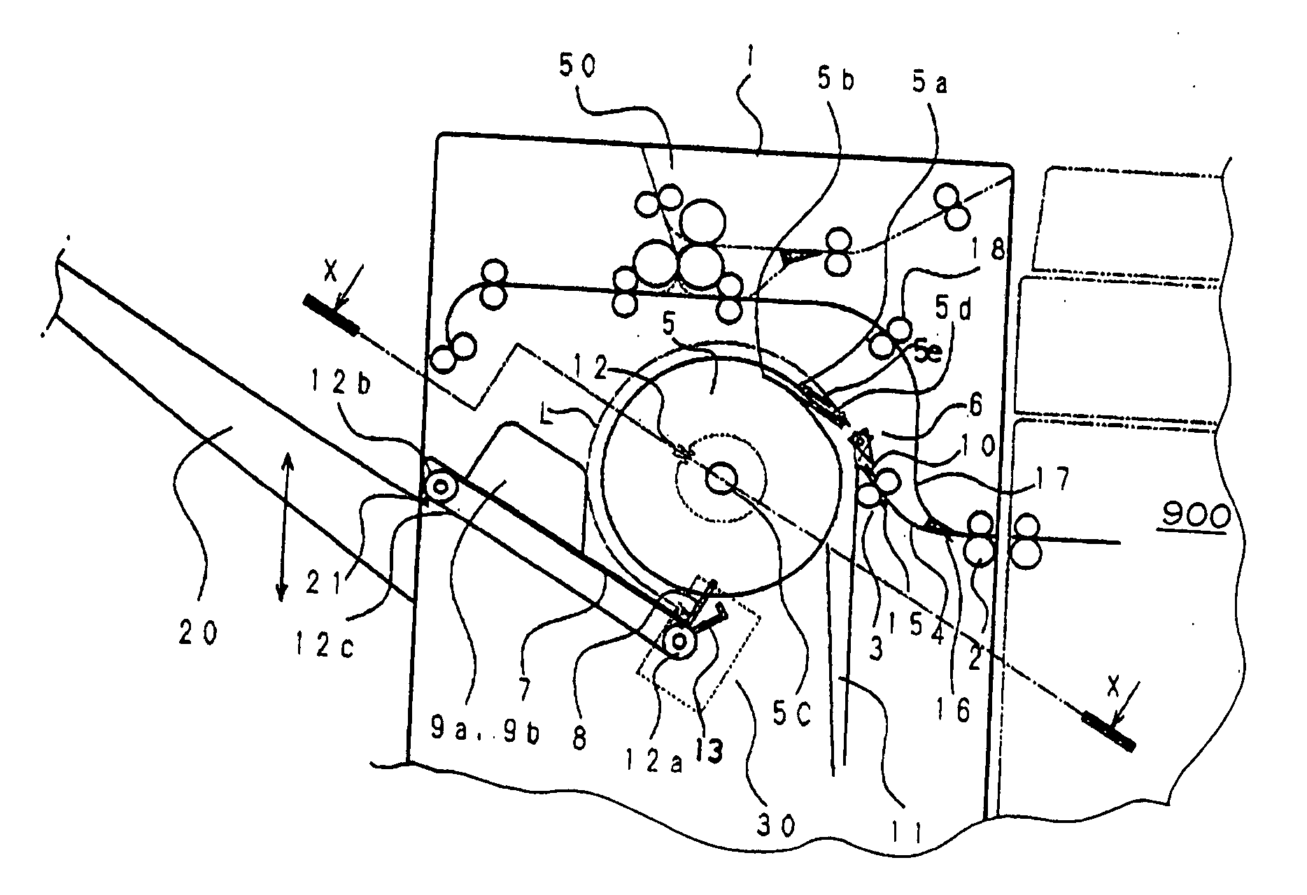
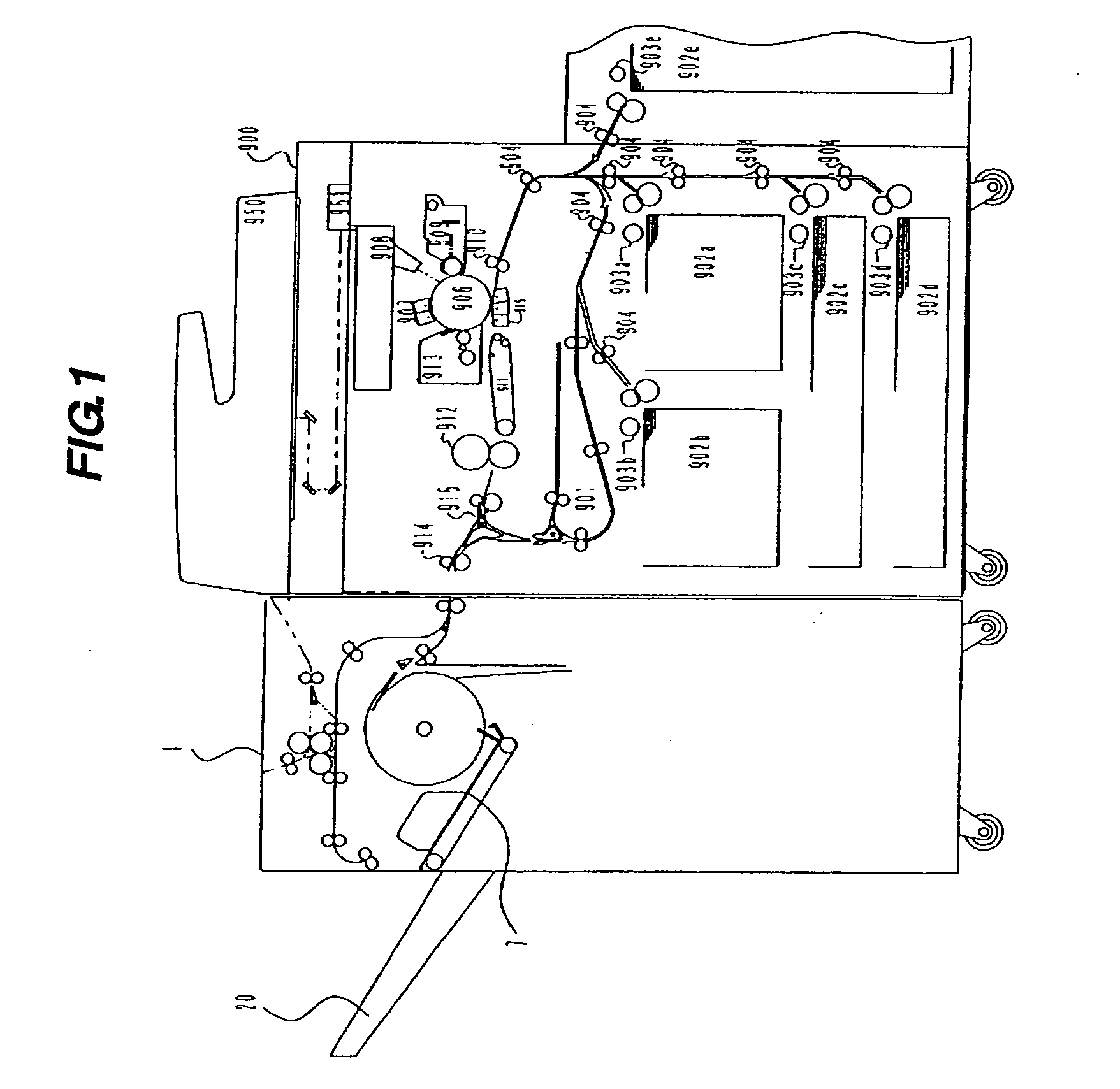
[0058] When the user specifies the staple sort mode (step: S1), the first sheet P1 formed with image shown with a broken line in the figure is discharged from the apparatus main body 900 of the image forming apparatus as shown in FIG. 10. The discharged sheet P1 is received by the entrance side rollers 2, 3 and conveyed to the conveyance paths 4, 10. The flappers 6 are at the position of the figure and convey the sheet P1 to the movement gripper 5. The movement gripper 5 is in a stopped state at the receiving position (step: S2). The movement gripper 5 is moved to the receiving position when not in the receiving position (step: S3). As the conveyance proceeds, the front end of the sheet P1 is guided to the gripper tapered surface 5d and enters the gripping portion 5a, and abuts against the abutment surface 5b of one of the two movement grippers 5 lined on the rotating shaft. The movement gripper 5 is still stopped over a predetermined time after the abutment, and the...

second embodiment

Sort Mode

[0071] The operation of when the sort mode in which the stapling is not performed is specified by the user will now be described. In this mode as well, two, or three or more sheets are stacked and accommodated in the processing tray 7 while being sequentially superimposed on the movement gripper 5, similar to the staple and sort mode. After the sheet of the last page is aligned, the stack conveying projection 13 immediately discharges the sheet bundle to the stack tray 20. Subsequently, the next subsequent sheet bundle is similarly divided and accommodated in the processing tray 7, but the aligning position in the sheet width direction is performed at a position different from the previous sheet bundle. This is so as to distinguish the previous sheet bundle when the subsequent sheet bundle is stacked in the stack tray 20. Therefore, the sheet bundle is stacked up to the last stack at the stack tray 20 while changing the aligning position in the sheet width direction on the ...


PUM


Abstract

The front ends of the plurality of sheets stacked on the processing tray are abutted against the stopper and are reliably aligned. The stack of a predetermined number of sheets to be accommodated in the processing tray is aligned and stacked all at once in the processing tray while being simultaneously gripped by the gripping portion 5a of the movement gripper in a plurality of sheet groups. The temporal margin is thereby produced compared to when aligning and stacking are performed one sheet at a time, and thus is effective in realizing the high speed process at low cost and maintaining high productivity.

Description

BACKGROUND OF THE INVENTION [0001] 1. Field of the Invention [0002] The present invention relates to a sheet processing apparatus (finisher) for performing processes such as alignment and stapling with respect to the image formed sheets discharged from an image forming apparatus such as a copying machine, facsimile machine, printer, complex machine and the like, and an image forming apparatus. [0003] 2. Description of the Related Art [0004] Conventionally, various sheet processing apparatuses have been proposed for stacking the sheets performed with image formation in the image forming apparatus while aligning the sheets on a processing tray, and conveying the sheets performed with the stapling process and the like to a stack tray different from the processing tray (see for example, Japanese Patent Application Laid-open No. 10-194582). Japanese Patent Application Laid-open No. 10-194582 discloses superimposing a few sheets at the beginning of the subsequent job discharged from the i...

Claims


Application Information

Patent Timeline
IPC IPC(8): B65H33/04
CPCB65H29/02B65H29/06B65H33/00B65H29/40B65H31/36B65H2404/655
Inventor HAYASHI, KENICHIOIKAWA, ATSUTERUTAMURA, KENICHISUGIURA, TAKASHIKAMIYA, DAISAKUWATANABE, KIYOSHIWATANABE, NAOTO
Owner CANON KK
Why Eureka
Try Eureka