Brake control apparatus and control method thereof

a technology of brake control apparatus and control method, which is applied in the direction of brake system, braking components, transportation and packaging, etc., to achieve the effect of high accuracy, high accuracy and accurate determination

Active Publication Date: 2007-05-17
TOYOTA JIDOSHA KK
View PDF2 Cites 34 Cited by
  • Summary
  • Abstract
  • Description
  • Claims
  • Application Information

AI Technical Summary

Benefits of technology

[0028] According to this aspect, while an operation is being performed on the brake operating member, the second cut valve is closed, and the first cut valve and the separation valve are opened. As a result, equal working fluid pressures act on the first pressure sensor and the second pressure sensor. Consequently, the accuracy in determining whether or not any one of the sensors has an abnormality on the basis of measured values of the sensors can be improved. Therefore, this determination can be performed with a higher accuracy than the determination as to whether the wheel cylinder pressure in accordance with the amount of brake operation is generated.
[0029] Furthermore, the control device may determine whether or not at least one of the first pressure sensor, the second pressure sensor, and the brake operation amount sensor has an abnormality based on the measured values. In this manner, the abnormality determination regarding the sensors is also performed, so that the determination as to whether the wheel cylinder pressure in accordance with the amount of brake operation is generated can be performed with higher accuracy.

Problems solved by technology

Furthermore, since the presence / absence of an abnormality is determined by operating the control device when the driver is not operating the brake, the driver does not perceive the change in the pedal feel associated with the determination.

Method used


Image

  • Brake control apparatus and control method thereof
  • Brake control apparatus and control method thereof
  • Brake control apparatus and control method thereof

Examples


Embodiment Construction

[0050] Hereinafter, best modes for carrying out the invention will be described in detail with reference to the drawings.

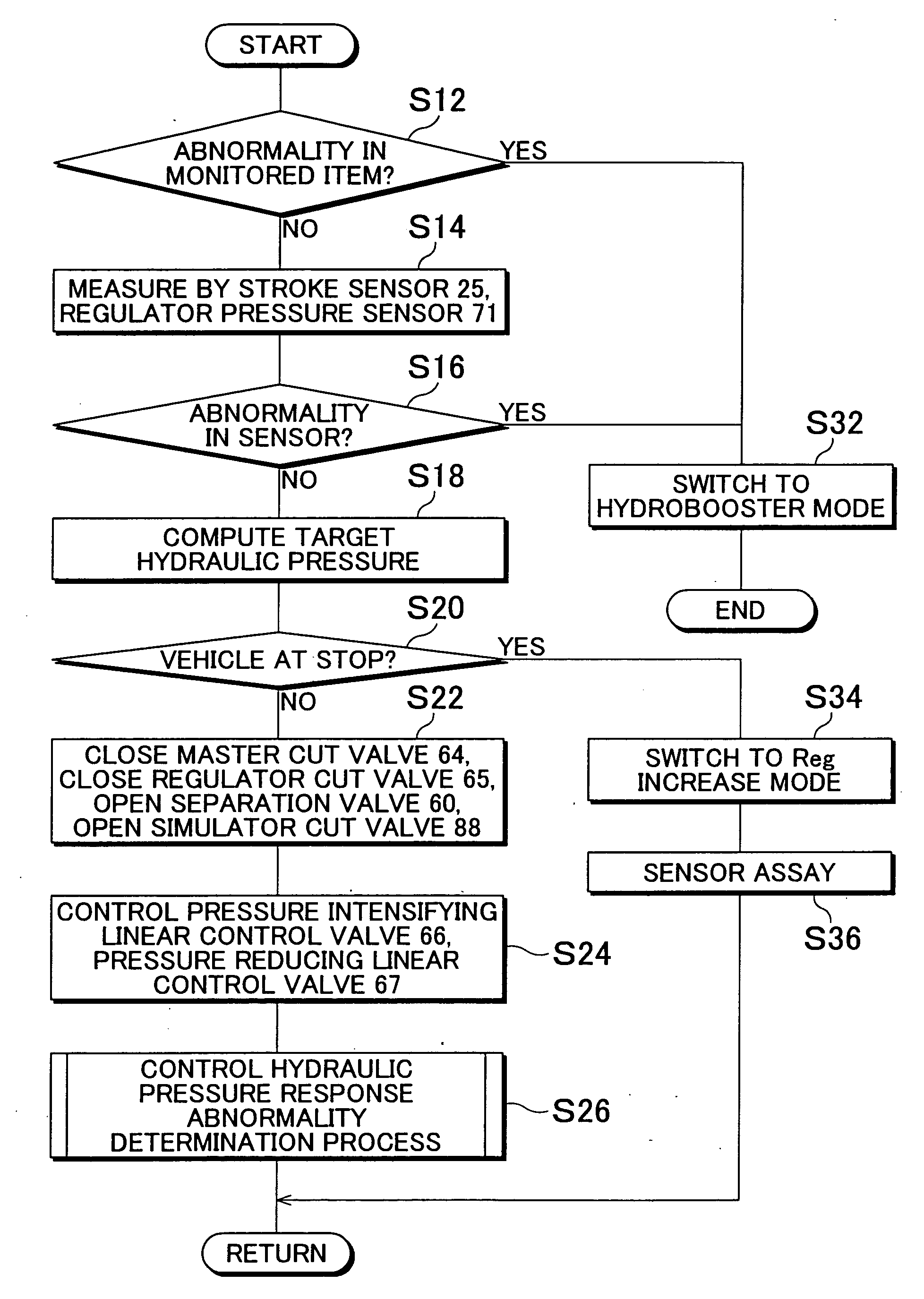
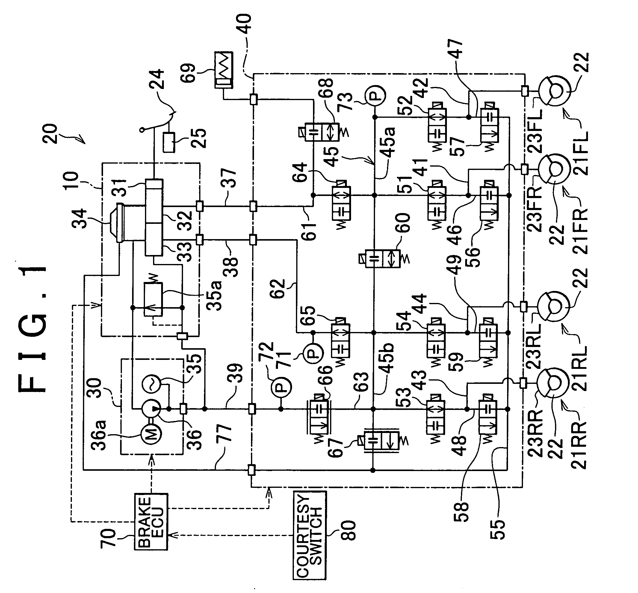
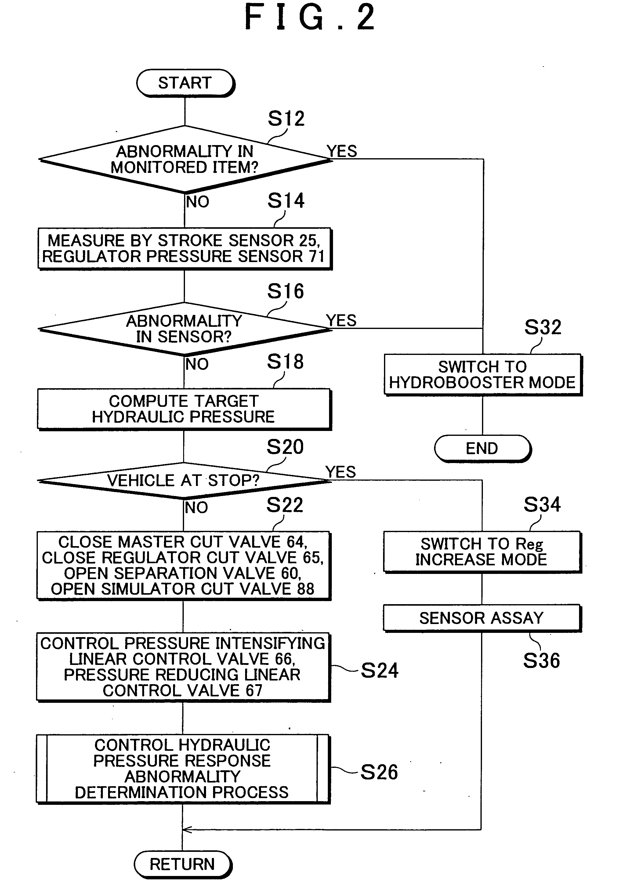
[0051]FIG. 1 is a system diagram showing a brake control apparatus 20 in accordance with an embodiment of the invention. The brake control apparatus 20 shown in this drawing constitutes a vehicular electronic control brake system (ECB), and controls the braking force applied to four wheels provided on a vehicle. The brake control apparatus 20 in accordance with this embodiment may be installed in, for example, a hybrid vehicle equipped with an electric motor and an internal combustion engine as running drive sources. In such a hybrid vehicle, the regenerative braking that brakes the vehicle by converting kinetic energy of the vehicle into electric energy, and the hydraulic braking by the brake control apparatus 20 can each be used to brake of the vehicle. The vehicle in this embodiment may execute a brake regeneration cooperative control to generate the desired b...


PUM


Abstract

A brake control apparatus has first and second wheel cylinders; a master cylinder unit; first and second systems; a separation valve; a pressure control mechanism that controls the working fluid pressure transferred to at least one of the first and second wheel cylinders independently of the brake operation, and a brake ECU. The brake ECU generates a differential pressure across the separation valve by operating the pressure control mechanism when there is no brake operation while a running drive source of a vehicle is stopped to determine whether the separation valve has a leakage abnormality.

Description

INCORPORATION BY REFERENCE [0001] The disclosure of Japanese Patent Application No. 2005-327938 filed on Nov. 11, 2005 including the specification, drawings and abstract is incorporated herein by reference in its entirety. BACKGROUND OF THE INVENTION [0002] 1. Field of the Invention [0003] The invention relates to a brake control apparatus that controls the braking force applied to wheels provided on a vehicle, and a control method thereof. [0004] 2. Description of the Related Art [0005] There has been a known brake hydraulic pressure control apparatus equipped with a separation valve that separates a hydraulic pressure circuit into a first system and a second system, and a pressure-intensifying linear control valve provided between the separation valve and a master cylinder in the first or second system (e.g., Japanese Patent Application Publication No. JP-A-Hei-11-115740). In this brake hydraulic pressure control apparatus, when the brake pedal is depressed after the ignition swit...

Claims


Application Information

Patent Timeline
Patent Type & Authority Applications(United States)
IPC IPC(8): B60T8/88
CPCB60T8/4081B60T8/885B60T8/90B60T17/22B60T2270/406Y10S303/02
Inventor OHKUBO, MASAYASUOTOMO, AKIHIROFUKASAWA, TSUKASA
Owner TOYOTA JIDOSHA KK
Why Eureka
Try Eureka