Drive bay heat exchanger

a heat exchanger and drive bay technology, applied in the direction of cooling/ventilation/heating modifications, electrical apparatus casings/cabinets/drawers, instruments, etc., can solve the problems of high speed operation, large amount of unwanted acoustic noise, annoying computer users, etc., and achieve the effect of convenient implementation

Active Publication Date: 2007-05-17
NVIDIA CORP
View PDF12 Cites 21 Cited by
  • Summary
  • Abstract
  • Description
  • Claims
  • Application Information

AI Technical Summary

Benefits of technology

[0009] The disclosed system may be advantageously disposed in any computing device whose chassis has a standard-sized drive bay, thereby enabling the system to be easily implemented across a wide variety of computing devices.

Problems solved by technology

One drawback of these conventional blower / fan cooling systems is that, as processors become more powerful and generate more heat, the fan has to be operated at very high speeds to generate the airflow through the air channels and over the heat sink necessary to cool the processor.
High speed operation tends to produce a substantial amount of unwanted acoustic noise, which is annoying to users of a computer.
Also, in some instances, these types of conventional cooling systems may not even be able to meet the heat dissipation requirements of certain high-performance processors.
Further compounding these issues is the fact that, while processors are becoming more powerful, the available space for cooling systems within computing devices is generally not increasing.
However, there are several challenges that need to be overcome to effectively implement a liquid cooling system in a computer system.
First, a liquid cooling system requires more space than an air cooling system.

Method used


Image

  • Drive bay heat exchanger
  • Drive bay heat exchanger
  • Drive bay heat exchanger

Examples


Embodiment Construction

)

[0015] All references to directions in describing parts, such as top and bottom are for convenience and not meant to limit embodiments of the invention in any way.

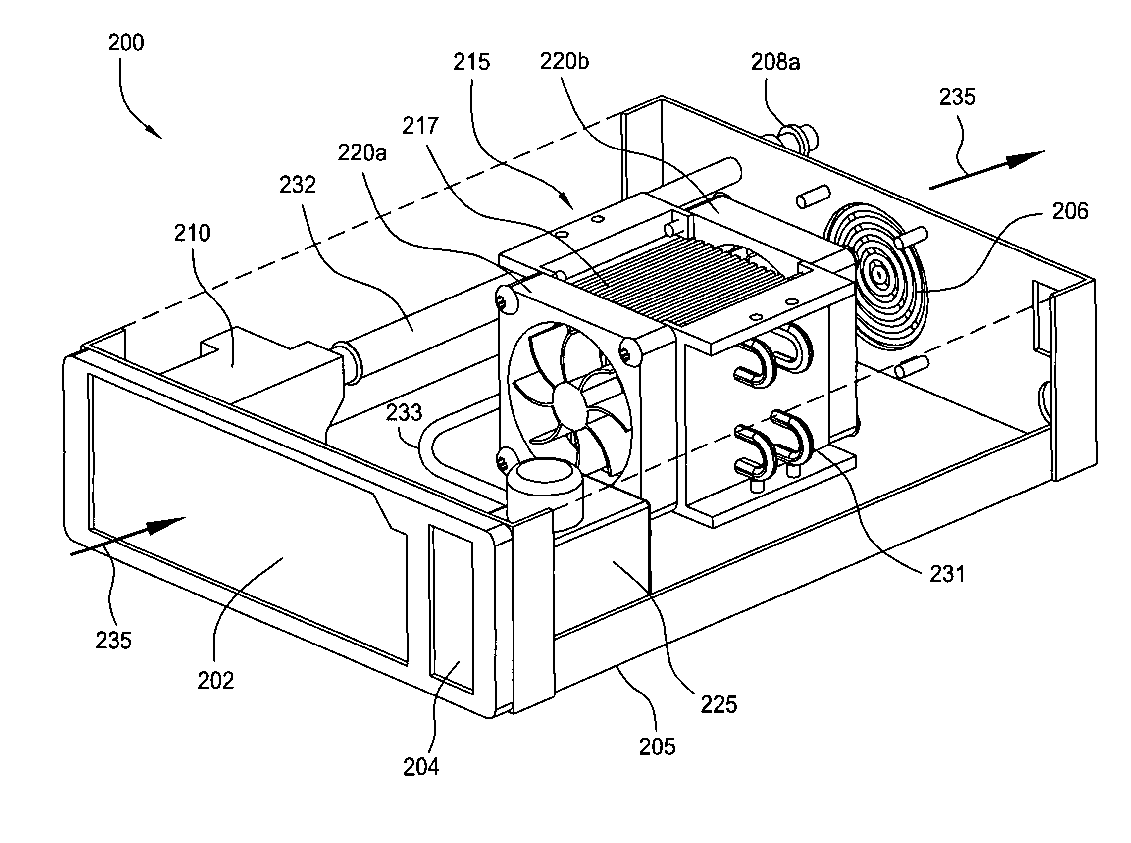
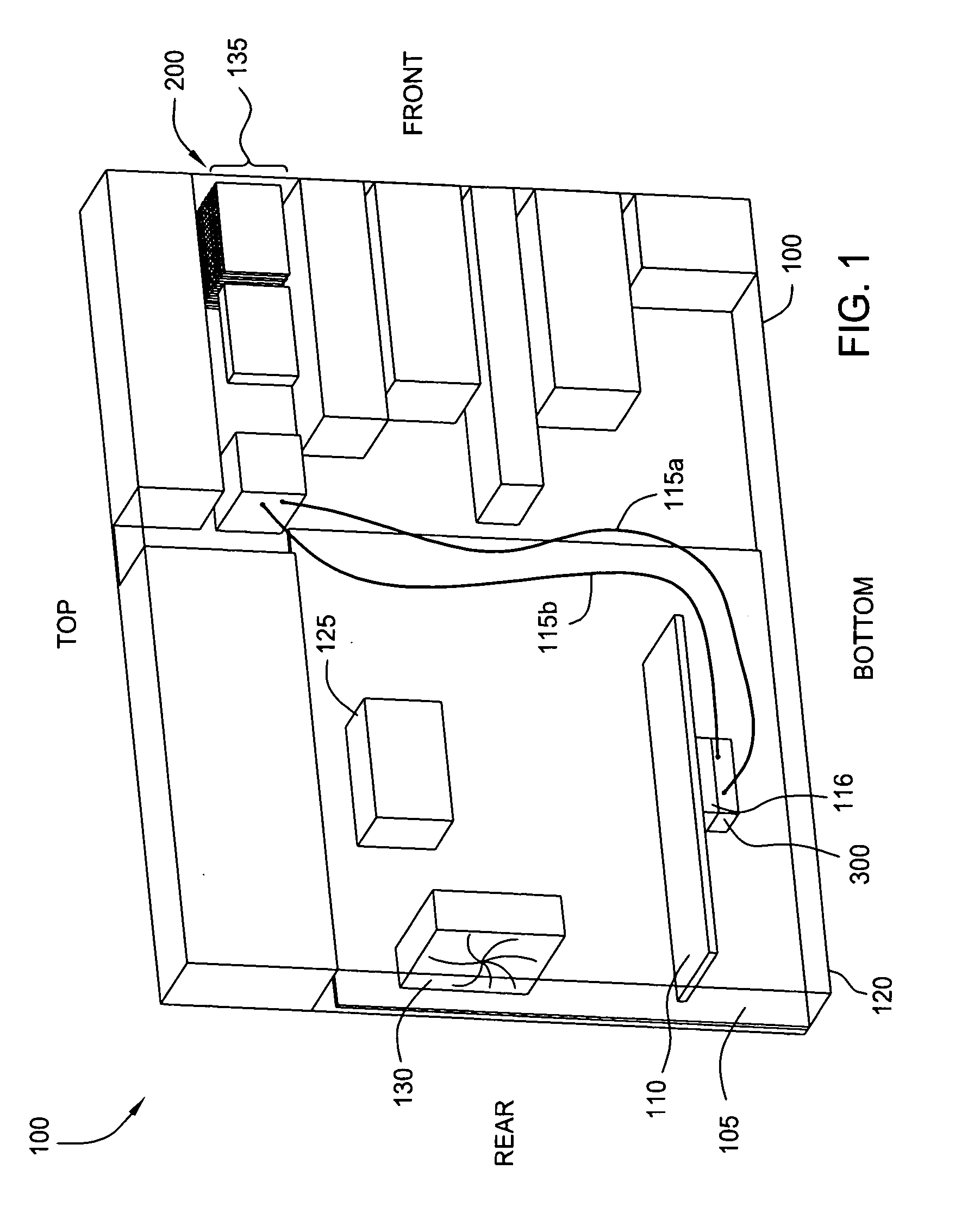
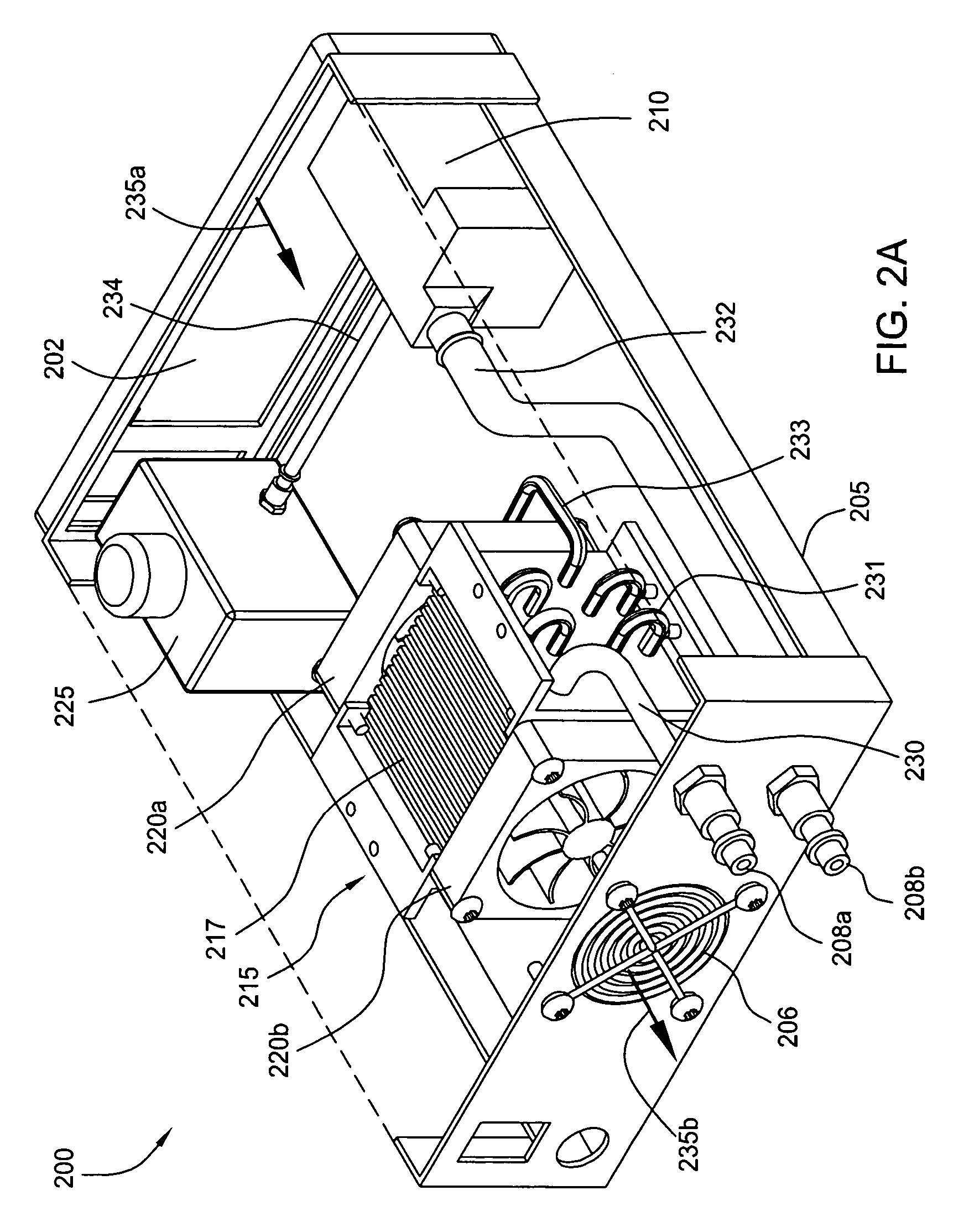
[0016]FIG. 1 is a schematic diagram illustrating a computing device 100 that includes a drive bay heat exchanger (DBHA) 200 and a graphics processing unit (GPU) 116, according to one embodiment of the present invention. As shown, the computing device 100 includes a housing 120, within which a motherboard 105 resides. Mounted on the motherboard 105 is a central processing unit (CPU) 125, a system fan 130 for removing heat from computing device 100. Motherboard 105 incorporates a graphics card 110 that enables computing device 100 to process graphics-related data for graphics intensive applications such as gaming applications. Graphics card 110 comprises a printed circuit board (PCB) upon which a plurality of circuit components (not shown), such as memory chips and the like, are mounted. In addition, mounted to one face of...


PUM


Abstract

The present invention represents a significant advancement in the field of cooling systems for computer hardware. One embodiment of a system for cooling a heat-generating device includes a housing sized to fit within a drive bay of a computing device, a heat exchanger disposed within the housing and configured to transfer heat from liquid to air, a fan disposed within the housing and configured to force air through the heat exchanger, and a pump disposed within the housing and configured to circulate a liquid through a cold plate sub-assembly and back to the heat exchanger. The cold plate sub-assembly is configured to be thermally coupled to the heat-generating device. The disclosed system may be advantageously disposed in any computing device whose chassis has a standard-sized drive bay, thereby enabling the system to be easily implemented across a wide variety of computing devices.

Description

BACKGROUND OF THE INVENTION [0001] 1. Field of the Invention [0002] This invention relates generally to cooling systems for computer hardware and more particularly to a heat exchanger system that may be implemented within the drive bay of a computing device. [0003] 2. Description of the Related Art [0004] Conventional cooling systems for heat generating devices that reside in a computing device, such as central processing units (CPUs) and graphic processing units (GPUs), typically include a heat sink disposed on the processor and a fan to direct air over the heat sink through channels formed by a series of fins disposed on top of the heat sink. In such a design, heat is transferred from the processor, to the heat sink and fins, and to the air flowing through the channels and over the heat sink. The heat is then dissipated into the surrounding environment as the air flows out of the channels and away from the processor. [0005] One drawback of these conventional blower / fan cooling sys...

Claims


Application Information

Patent Timeline
Patent Type & Authority Applications(United States)
IPC IPC(8): G06F1/20
CPCG06F1/187G06F1/20G06F2200/201
Inventor STEFANOSKI, ZORAN
Owner NVIDIA CORP
Why Eureka
Try Eureka