High speed and direct driven rotating equipment for polyolefin manufacturing

a technology of rotating equipment and polyolefin, which is applied in the direction of clay mixing apparatus, rotary stirring mixer, mixing/kneading with horizontally mounted tools, etc., can solve the problems of consuming energy, requiring maintenance time and expense, and expensive addition of components

Inactive Publication Date: 2007-05-17
UNIVATION TECH LLC
View PDF57 Cites 32 Cited by
  • Summary
  • Abstract
  • Description
  • Claims
  • Application Information

AI Technical Summary

Benefits of technology

[0008] Apparatus and methods for extruding polymer are provided. In at least one specific embodiment, the apparatus includes a housing, two or more rotatable members at least partially contained within the housing, where each rotatable member having a shaft coupled thereto. The apparatus also includes a motor having a drive shaft directly coupled to the shaft of at least one of the rotatable members such that the rotatable member rotates at a speed of the motor drive shaft. The rotatable members are preferably non-intermeshing and counter-rotating
[0009] In at least one other specific embodiment, the apparatus includes a first housing having two or more screws contained therein. A first motor is directly coupled to at least one of the two or more screws and adapted to rotate the two or more rotatable screws. A second housing is provided and is in fluid communication with the first housing. The second housing includes two or more gears contained therein. A second motor is directly coupled to at least one of the two or more gears and adapted to rotate the two or more rotatable gears
[0010] In at least another specific embodiment, the method for polyolefin production includes directing a polyolefin through a twin screw extruder or continuous mixer to provide a molten polymer where the twin screw extruder or continuous mixer includes a housing having two or more screws contained therein; and a motor directly co

Problems solved by technology

Such additional components are expensive, require maintenance time and expense, consume energy, and often lack in efficiency.
Also, such components have large space requirements

Method used


Image

  • High speed and direct driven rotating equipment for polyolefin manufacturing
  • High speed and direct driven rotating equipment for polyolefin manufacturing
  • High speed and direct driven rotating equipment for polyolefin manufacturing

Examples


Embodiment Construction

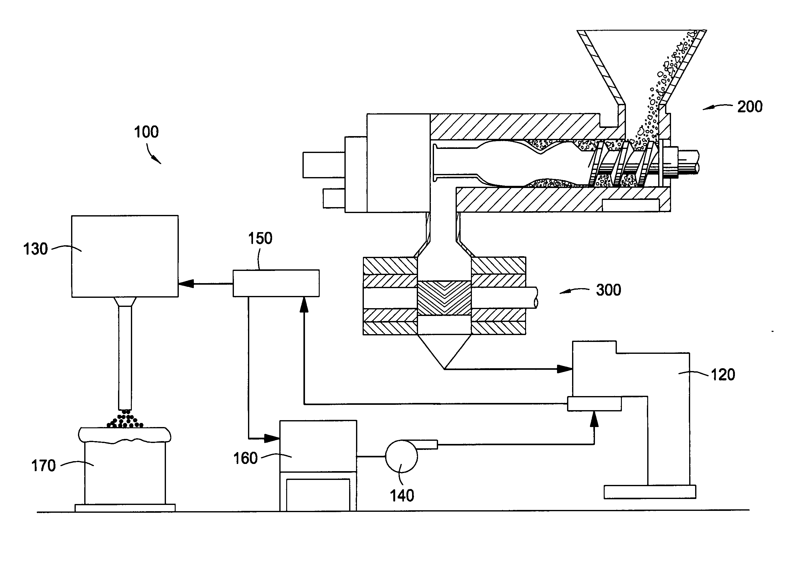
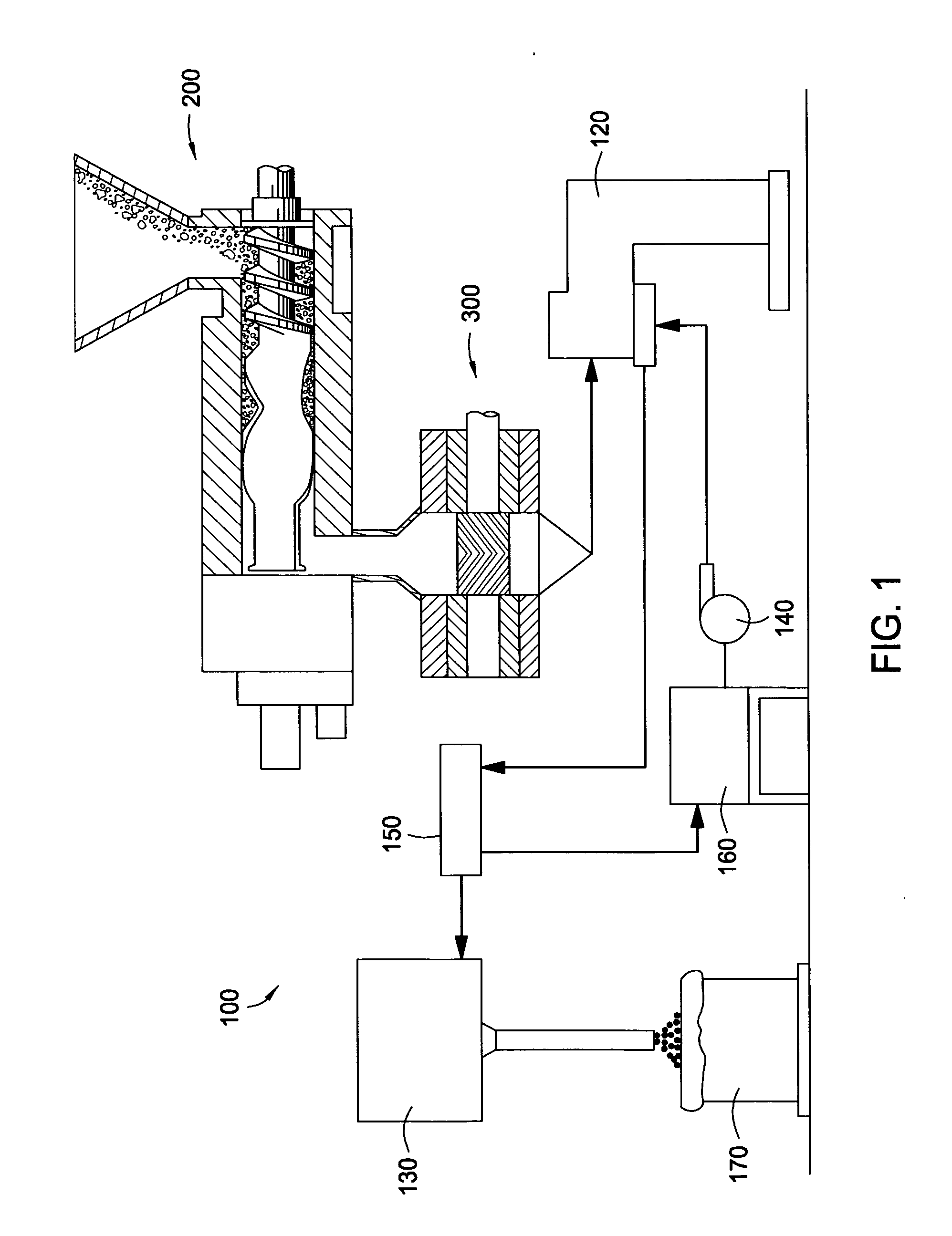
[0018]FIG. 1 is a schematic diagram showing an illustrative polymer pelletizing system 100. The pelletizing system 100 includes one or more pelletizers 120, drier systems 130, pumps 140, screens 150, surge tanks 160, material containers 170, continuous mixers 200, and gear pumps 300. In operation, a polymer is introduced to the mixer 200 where the polymer is melted and mixed. The polymer then passes from the mixer 200 to the gear pump 300. The gear pump 300 passes the molten polymer to the pelletizer 120. Pelletizers are well known, and any pelletizer or pelletizing system can be used. Preferably, an underwater pelletizer commercially available from Berstorff, Coperion W&P, Farrel, Gala, Japan Steel Works, Kobe Steel, and so on. At the discharge end of the pelletizer 120, the polymer is slurried to the drier system 140 through a hydraulic loop containing a pump 140, separator screen 150 and surge tank 160. The screen 150 separates the conveying liquid (water) from the pelletized pol...


PUM

PropertyMeasurementUnit
Residence timeaaaaaaaaaa
Angular velocityaaaaaaaaaa

Abstract

An apparatus and method for melting polymer is provided. In at least one embodiment, the apparatus includes a housing, two or more rotatable members at least partially contained within the housing, where each rotatable member having a shaft coupled thereto. The apparatus also includes a motor having a drive shaft directly coupled to the shaft of the rotatable members such that the rotatable members rotate at a speed of the motor drive shaft. The rotatable members are preferably non-intermeshing and counter-rotating.

Description

BACKGROUND OF THE INVENTION [0001] 1. Field of the Invention [0002] Embodiments of the present invention generally relate to apparatus and methods for producing polymer. More particularly, embodiments of the present invention relate to apparatus and methods for extruding polyolefin using high speed, directly driven rotating equipment. [0003] 2. Description of the Related Art [0004] Continuous mixers are the mainstay of many commercial polyolefin pelletizing production lines. A continuous mixer is different from an extruder in that continuous mixers are generally used only to melt and mix the resin, while extruders further provide pressure generation to force the molten resin through a die. Like extruders, continuous mixers can have one or multiple screws. [0005] General features that distinguish various twin-screw mixers from other mixers are the relative direction of rotation and the degree of intermeshing of the rotors. Twin-screw mixers having rotors that rotate in the same direc...

Claims


Application Information

Patent Timeline
IPC IPC(8): B28C7/16B29C48/38B29C48/395
CPCB29B7/465B29B7/7485B29C47/0004B29C47/0011B29C47/367B29C47/38B29C47/404B29C47/364B29C48/022B29C48/04B29C48/37B29C48/387B29C48/395B29C48/404B29C48/405B29C48/40B29B7/488
Inventor NEUBAUER, ANTHONY CHARLES
Owner UNIVATION TECH LLC
Why Eureka
Try Eureka