
Switch-type imaging fiber apparatus and branch-type imaging fiber apparatus

Inactive Publication Date: 2007-05-17
NATIONAL UNIVERSITY
View PDF5 Cites 39 Cited by
  • Summary
  • Abstract
  • Description
  • Claims
  • Application Information

AI Technical Summary

Benefits of technology

[0011] The present invention is mainly based on the assumption that a plurality of fibers (endoscopes) are inserted in a biological body. A first object of the present invention is to provide a switch-type imaging fiber apparatus in which the incidence of light on and the detection of light in the plurality of fibers are controlled to be switched by the single apparatus to enable chronological observation of the states of a multitude of affected areas in a biological body, without increasing the size of the apparatus and by a simple switching operation.
[0012] A second object of the present invention is to provide a branch-type imaging fiber apparatus in which the incidence of light on and the detection of light in the plurality of fibers are ON-OFF controlled by the single apparatus to enable simultaneous and chronological observation of a multitude of affected areas in a biological body, without increasing the size of the apparatus and by a simple operation.
[0022] According to the configurations of the first to sixth aspects of the present invention, the states of a multitude of affected areas in a biological body can be chronologically observed, without increasing the size of the apparatus and by a simple switching operation. Further, it is possible to make the number of the IFs unlimited, and to focus the light to be switched on one of the IFs. If the GLV is employed, the IFs can be separated by color.
[0023] According to the configurations of the seventh to ninth aspects of the present invention, even if the number of the imaging fibers is large, the structure of the apparatus can be made simple. Accordingly, it is possible to reduce the size of the apparatus and switch the light at a high speed.
[0024] The switch-type imaging fiber apparatus and the branch-type imaging fiber apparatus are in common in that the both apparatuses enable chronological observation of the states of the multitude of affected areas in the biological body, without increasing the size of the apparatuses. The switch-type imaging fiber apparatus switches all of the light to be input and supplies the switched light to each of the image fiber devices, and thus can make a larger amount of light incident on the respective imaging fibers than the branch-type imaging fiber apparatus does. Meanwhile, the branch-type imaging fiber apparatus divides the light and makes the divided lights incident on the respective imaging fibers. Thus, the amount of the light incident on the respective imaging fibers is smaller than in the switch-type imaging fiber apparatus. However, the branch-type imaging fiber apparatus can employ the crystal shutter as the structure for dividing the light, and thus is advantageous over the switch-type imaging fiber apparatus in terms of further reduction in size of the apparatus.

Problems solved by technology

Thus, the size of the apparatus is increased and the operation of the apparatus becomes complicated, which is inefficient.
Further, in a case in which treatments or the like are performed on the affected areas, i.e., the observation targets existing at a plurality of locations, and the process of and the causal relationship between the treatments or the like are examined, the above configuration is inconvenient to view the observation images obtained by the respective imaging fibers in terms of the chronological change.
However, the above proposal is for observing the inner wall of the intestinal tract with the multitude of objective fiberscopes 10, and is not the apparatus for observing, substantially at the same time, a multitude of affected areas positioned apart from one another in a biological body.
Thus, the above proposal is not for applying light to observation targets from the respective fibers and receiving resultant reflected light.
Therefore, the apparatus is not provided with a portion including a light source and a switching mechanism for making the light enter into or exit from the respective fibers at a bundled part of the image guides.
Further, the fibers cannot be used as fibers for observing respective affected areas in a biological body.

Method used


Image

  • Switch-type imaging fiber apparatus and branch-type imaging fiber apparatus
  • Switch-type imaging fiber apparatus and branch-type imaging fiber apparatus
  • Switch-type imaging fiber apparatus and branch-type imaging fiber apparatus

Examples


Embodiment Construction

[0038] Embodiments of the present invention will now be described in detail with reference to the drawings.

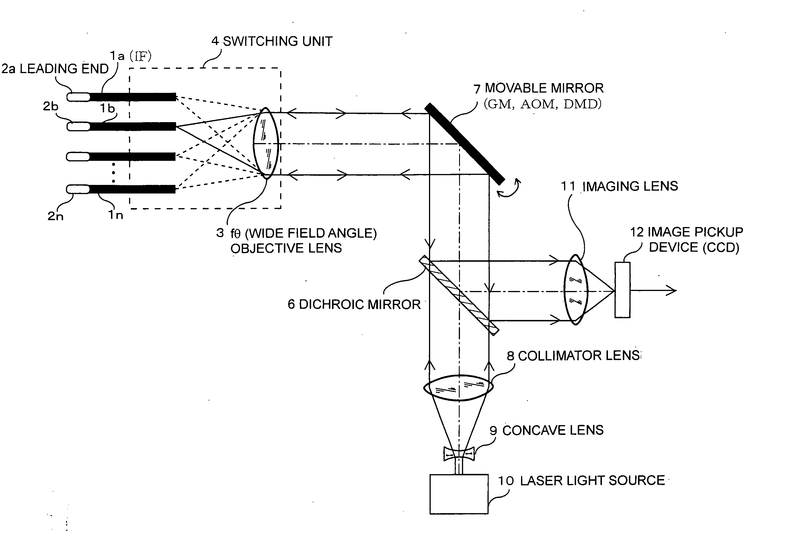
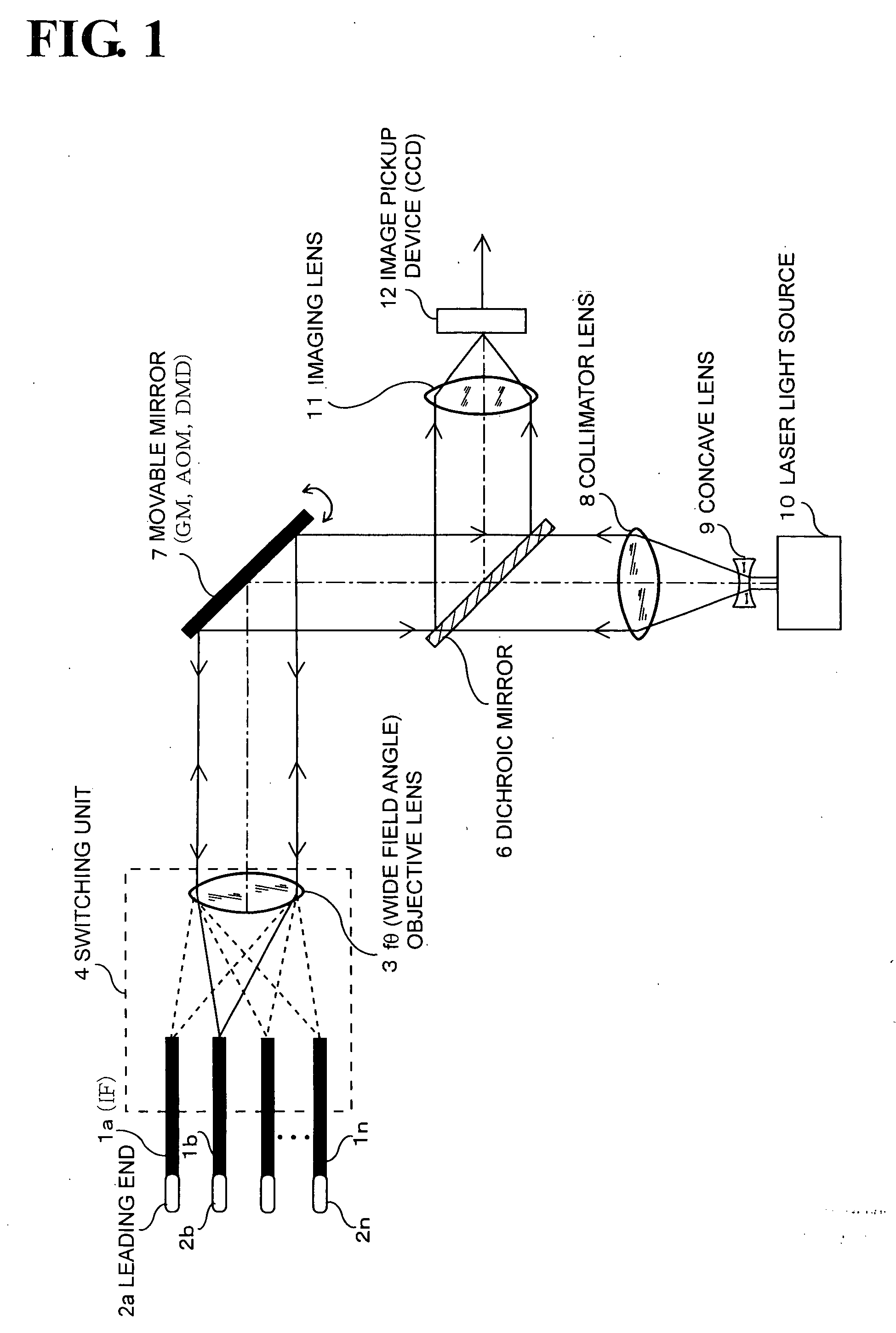
[0039]FIG. 1 is a schematic diagram illustrating an embodiment of a switch-type imaging fiber apparatus according to the present invention. The present embodiment uses an optical switching system and employs a movable mirror, which is a GM (galvanometer) in the present example.

[0040] Reference numerals 1a to 1n indicate imaging fibers (hereinafter referred to as the “IFs”). Each of leading end portions 2a to 2n is attached with an optical system for applying light to an observation target and taking in resultant reflected light. The other end of each of the IFs 1a to 1n is formed with an opening for taking in the light, and is disposed at a predetermined position within a switching unit 4. Each of the IFs la to 1n is formed by bundling together a multitude of optical fiber strands, and has predetermined elasticity (i.e., flexibility), capable of being bent with a curvature se...


PUM


Abstract

A switch-type imaging fiber apparatus and a branch-type imaging fiber apparatus are provided. Light emitted from a laser light source is made incident on an opening of an IF (image fiber) guided by a GM (galvanometer), output from an optical system provided at a leading end portion of the IF, and applied to an observation target. The light reflected by the observation target is sent back to the IF, transformed into parallel light by an fθ objective lens, reflected by a dichroic mirror, made incident on an image pickup device (CCD) via an imaging lens, and can be observed on a monitor. The GM is controlled to switch to make the light incident on the opening of an arbitrary one of a plurality of IFs. Accordingly, observation can be performed by focusing the light solely on the arbitrary IF.

Description

BACKGROUND OF THE INVENTION [0001] 1. Field of the Invention [0002] The present invention relates to a switch-type imaging fiber apparatus which inserts imaging fibers into a plurality of introduction holes formed in a biological body or the like and switches laser light or the like incident on end surfaces of the respective imaging fibers to thereby observe affected areas or the like located at the leading ends of the imaging fibers. The present invention also relates to a branch-type imaging fiber apparatus which inserts imaging fibers into a plurality of introduction holes drilled in a biological tissue or the like and allows or blocks the incidence of laser light or the like through an ON-OFF mechanism provided at end surfaces of the respective imaging fibers to thereby observe affected areas or the like located at the leading ends of the imaging fibers. [0003] 2. Description of the Related Art [0004] A system has been in practical use which forms an introduction hole reaching a...

Claims


Application Information

Patent Timeline
IPC IPC(8): A61B1/06G02B6/06
CPCA61B1/00117A61B1/07A61B1/3132G02B6/06G02B6/3504G02B6/3508G02B6/3512G02B6/353G02B6/3598A61B1/043A61B1/00165
Inventor TERAKAWA, SUSUMUSAKURAI, TAKASHIWAKAZONO, YOSHIHIKOHIRUKAWA, HIDEOTANAAMI, TAKEO
Owner NATIONAL UNIVERSITY
Features
  • Generate Ideas
  • Intellectual Property
  • Life Sciences
  • Materials
  • Tech Scout
  • Unparalleled Data Quality
  • Higher Quality Content
  • 60% Fewer Hallucinations
Learn More