Longitudinally reinforced cured in place liner and reinforced coating

a technology of longitudinal reinforcement and longitudinal reinforcement, which is applied in the direction of pipe elements, mechanical equipment, other domestic objects, etc., can solve the problems of deterioration of the pipe itself, leakage in the existing conduit, and the deterioration of the conduit itsel

Inactive Publication Date: 2007-05-24
INA ACQUISITION
View PDF16 Cites 34 Cited by
  • Summary
  • Abstract
  • Description
  • Claims
  • Application Information

AI Technical Summary

Benefits of technology

[0017] The coated scrim layer provides increased longitudinal reinforcement. This increase in longitudinal strength allows for pulling-in of long lengths of liner, and substantially reduces stretch of the resin impregnated liner during pull-in. The impermeable coating applied to the scrim is a polyolefin or other material that will withstand temperatures during steam cure of the liner. The coated scrim as the outer impermeable layer increases and evens out the stress across the entire circumference of the coated scrim layer and provides better performance in reducing longitudinal stretch as the warp scrim yarns and coating act more like a composition than the separate scrim and film layers.
[0020] Another object of the invention is to add a coated scrim during the manufacture of a CIPP liner that will limit longitudinal stretch without reducing circumference stretch.
[0021] A further object of the invention is to provide an improved method of manufacture of a longitudinally reinforced cured in place liner by disposing a coated scrim layer on the outer layer of resin absorbent material.
[0022] Yet another object of the invention is provide an improved method of continuously manufacturing a longitudinally reinforced resin impregnated cured in place liner having an inner impermeable layer and a coated scrim layer.

Problems solved by technology

It is generally well known that existing conduits and pipelines, particularly underground pipes, such as sanitary sewer pipes, storm sewer pipes, water lines and gas lines that are employed for conducting fluids frequently require repair due to fluid leakage.
The leakage in the existing conduit may be due to improper installation of the original pipeline, or deterioration of the pipe itself due to normal aging, or the effects of conveying corrosive or abrasive material.
Cracks at, or near pipe joints may be due to environment conditions such as earthquakes, or the movement of large vehicles on the overhead surface, or similar natural or man-made vibrations, or other such causes.
Regardless of the cause, such leakages are undesirable and may result in waste of the fluid being conveyed within the pipeline, or result in damage to the surrounding environment and possible creation of dangerous public health hazards.
If the leakage continues it can lead to structural failure of the existing conduit due to loss of soil and side support of the conduit.
Because of ever increasing labor and machinery costs, it is increasingly more difficult and less economical to repair underground pipes or portions that may be leaking by digging up the existing pipe and replacing the pipe with a new one.
However, the process still requires inversion of a bladder into the pulled-in impregnated liner.
This process avoids the inversion below grade, but is severely limited into the length of lining that can be laid out above ground prior to pulling-in.
The disadvantages here involves the difficulty faced when trying to impregnate the resin impregnable material disposed between the inner and outer impermeable coatings.
The increase in weight of the liner for larger diameter liners makes the load required for pull-in even more staggering.
Thus, there are significant limitations on the lengths of liner that can be pulled in.
While these suggestions to increase longitudinal strength are available, there are difficulties in handling webs and attaching them to one of the resin absorbent layers as a heavy web tends to hinder impregnation and reduce the circumferential stretch need for CIPP installation.

Method used


Image

  • Longitudinally reinforced cured in place liner and reinforced coating
  • Longitudinally reinforced cured in place liner and reinforced coating
  • Longitudinally reinforced cured in place liner and reinforced coating

Examples


Embodiment Construction

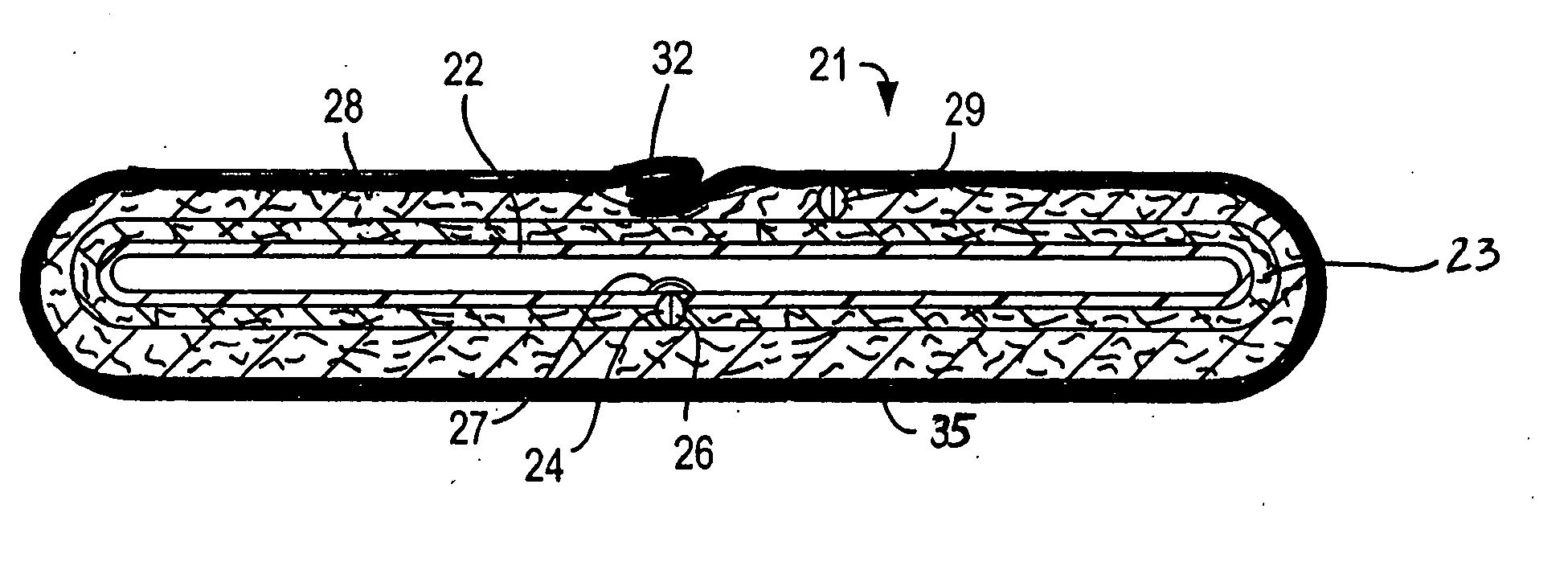
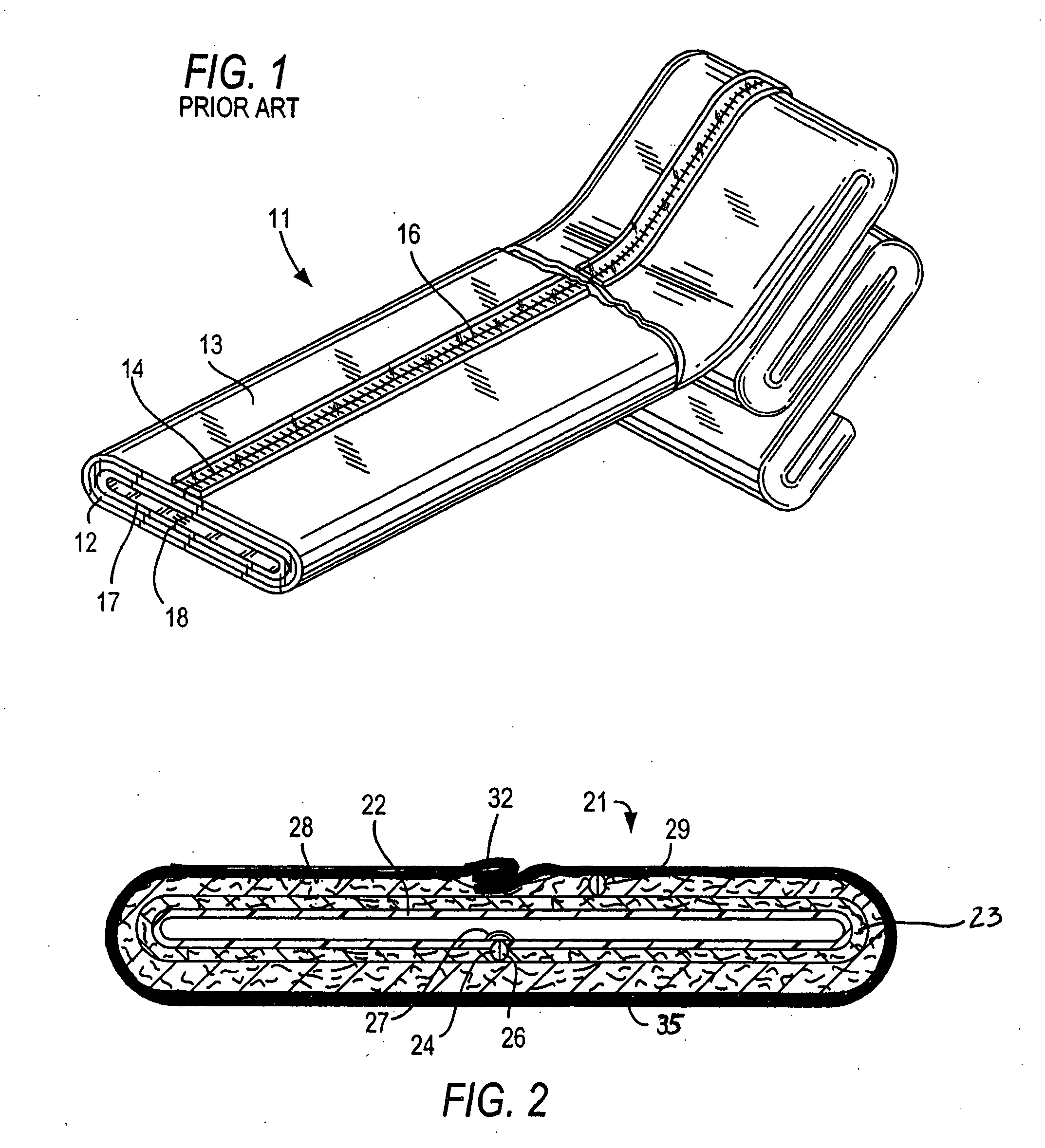
[0038] A resin impregnated cured in place liner prepared in accordance with the invention has a longitudinal reinforcing coated scrim layer as the outer impermeable layer. When prepared with an integral internal impermeable layer, it can be installed by the pull-in-and-inflate method and be inflated and cured with a heated fluid without the use of an inflation bladder. A liner with inner impermeable longitudinal reinforcing coated scrim layer may be prepared in continuous lengths. It may be impregnated as it is assembled in view of the increased effort necessary to impregnate a flattened liner having a resin absorbent material between an inner and an outer coating using conventional vacuum impregnation technology.

[0039]FIG. 1 illustrates a flexible cured in place liner 11 of the type generally in use today and well known in the art. Liner 11 is formed from at least one layer of a flexible resin impregnable material, such as a felt layer 12 having an outer impermeable polymer film l...


PUM

PropertyMeasurementUnit
diameteraaaaaaaaaa
weightaaaaaaaaaa
lengthaaaaaaaaaa

Abstract

A longitudinally reinforced resin impregnated cured in place liner with at least an outer impermeable layer of a coated reinforcing scrim to limit longitudinal stretch is provided. A continuous length of resin impregnable liner is provided in lay flat condition and impregnated. The impregnated liner is then fed into a tubular former where a resin impermeable coated scrim in tubular form having greater strength in the warp direction than in the weft direction is fed into a tubular form, sealed and continuously inverted about the inner tubular member so that the inverted wrapping envelopes the tubular member. The reinforced liner may have an integral inner impermeable layer that may also be longitudinally reinforced is installed in an existing pipeline.

Description

BACKGROUND OF THE INVENTION [0001] This invention relates to cured in place liners for trenchless rehabilitation of existing conduits and pipelines, and more particularly to a cured in place liner longitudinally reinforced with a resin impermeable coated scrim on the outer surface of a liner with an inner impermeable layer, the liner suitable for trenchless rehabilitation of existing conduits. [0002] It is generally well known that existing conduits and pipelines, particularly underground pipes, such as sanitary sewer pipes, storm sewer pipes, water lines and gas lines that are employed for conducting fluids frequently require repair due to fluid leakage. The leakage may be inward from the environment into the interior or conducting portion of the pipelines. Alternatively, the leakage may be outward from the conducting portion of the pipeline into the surrounding environment. In either case of infiltration or exfultration, it is desirable to avoid this type of leakage. [0003] The le...

Claims


Application Information

Patent Timeline
Patent Type & Authority Applications(United States)
IPC IPC(8): B29C65/00
CPCB29C53/48B29C63/185B29C65/02B29C66/1122B29C66/43B29C66/80B29D23/001B29L2023/006F16L55/1651F16L55/1656B29C65/00B29C66/112B29C66/1142B29C66/135B29C66/4322B29C66/49B29C66/5326B29C66/71B29K2077/10B29K2077/00B29K2075/00B29K2067/00B29K2027/06B29K2023/12B29K2023/06B29K2023/00
Inventor DRIVER, FRANKLIN THOMASWANG, WEIPING
Owner INA ACQUISITION
Why Eureka
Try Eureka