Towed Vehicle Braking Apparatus

a technology for towed vehicles and brakes, applied in braking systems, analogue processes for specific applications, instruments, etc., can solve problems such as limiting the life span, reducing performance, and failure of the towing vehicle's brakes, and achieve the effect of effectively actuating the towed vehicle's brakes

Active Publication Date: 2007-05-24
HOPKINS MFG
View PDF68 Cites 41 Cited by
  • Summary
  • Abstract
  • Description
  • Claims
  • Application Information

AI Technical Summary

Benefits of technology

[0017] It is another aspect of the present invention to provide an auxiliary braking system that allows for real time, remote adjustment of various braking parameters while in transit, thereby alleviating the need for the operator to manually adjust settings of the system. In one embodiment of the invention, such parameters include, among other things, the sensitivity of the response of an inertia sensing device included in the auxiliary braking device that is used to activate the unit and define the amount of braking pressure. A remote control in the towing vehicle may be employed to transmit an RF signal relating to the desired parameter to the auxiliary braking apparatus.
[0026] It is still yet another aspect of the present invention to provide an auxiliary braking apparatus that allows for the monitoring of the apparatus' compressor run time to identify possible unit inefficiencies and to anticipate failure. For example, unless there is an appreciable audible hiss, pneumatic pressure leaks are undetectable. Some leakage can be tolerated because to fashion a leak-proof system would be cost prohibitive. The drawback of leakage is that the compressor of the apparatus must continually run to replenish the amount of fluid or gas in the reservoir, which is associated with wear on the compressor and / or excessive drain on the vehicle's battery. In one embodiment of the present invention, the run time of the compressor is monitored and compared with a preset, ideal run time. Generally, if the monitored runtime is greater than the preset value, the operator of the towed vehicle is notified either by an indicator on the apparatus or the remote control unit. Identification of longer than expected compressor run times allows the operator to investigate whether leaks and / or other mechanical failures have occurred in the system, thereby circumventing the potentially catastrophic situation wherein the compressor fails and the towed vehicle's bralkes are not applied.

Problems solved by technology

The towed vehicle is essentially dead weight that pushes the towing vehicle when the operator tries to slow or stop, which can limit the life span, cause decreased performance or cause failure of the towing vehicle's brakes.
While this information may be useful, the operator remains uninformed about equally important issues, such as whether the supplemental braking system is functioning efficiently within desired parameters.
One drawback of auxiliary braking systems of the art is that none allow the operator to control particular braking parameters.
Since the auxiliary brake apparatus is not located in the towing vehicle and typically the towed vehicle is unoccupied while in transit, the operator is generally unaware of whether the auxiliary braking apparatus has fully released the brake of the towed vehicle when supplemental braking is not required.
If the brake pedal is not fully retracted during non-use, excess strain is put on the towing vehicle as well as needless wear and tear on the brakes of the towed vehicle.
Similarly, operators of the towing vehicle are also generally unaware as to whether such units are working efficiently and / or are about to fail.
Many problems are associated with this corded configuration however.
For example, the operator can become inadvertently entangled in the cord, the cord typically prevents the unit from being placed in the operator's line of sight, and electrical interference with the towing vehicle's electrical system can occur.
Another drawback is that auxiliary brake systems of the art are often susceptible to operator error.
While the lack of electrical power will generally prevent accidental discharge of the unit, once power is restored to the unit for example, when the device is plugged into a cigarette lighter of the towed vehicle, there is a risk that the unit could immediately activate.
There is no way, however, to ensure that the operator will remember to perform this depressurizing step.
Another problem inherent to many auxiliary braking systems is that they are designed to be used with a “dead” brake pedal in the towed vehicle.
If the vacuum is not relieved and the auxiliary braking system is activated, excessive braking of the towed vehicle can occur that can damage the towed vehicle.
Even if an operator remembers to initially release the vacuum brake reservoir pressure, he or she often later forgets to perform this necessary operation once the auxiliary braking unit has been installed.
If not relieved, excessive, unwanted braking could occur in the towed vehicle.
Many operators, however, either forget to install this switch or ignore state mandate.
Another problem inherent to auxiliary brake systems relates to their ability to react and apply the towed vehicle's brakes as quickly as possible.
Conventional auxiliary braking apparatus do not take this non-braking stage into account when applying braking pressure and are thus not as effective as they could be.

Method used


Image

  • Towed Vehicle Braking Apparatus
  • Towed Vehicle Braking Apparatus
  • Towed Vehicle Braking Apparatus

Examples


Embodiment Construction

[0045] Various illustrative embodiments of the present invention will now be discussed. It is envisioned that the improvements described herein can be tailored to many different types of auxiliary braking systems (e.g., pneumatic, hydraulic, etc.). Thus, the following descriptions of embodiments of the present invention are meant to clarify how the improvements described herein could be employed in a conventional system and as such, any discussion of the type of the individual components of an auxiliary braking system are not intended to limit the scope of the present invention in any manner.

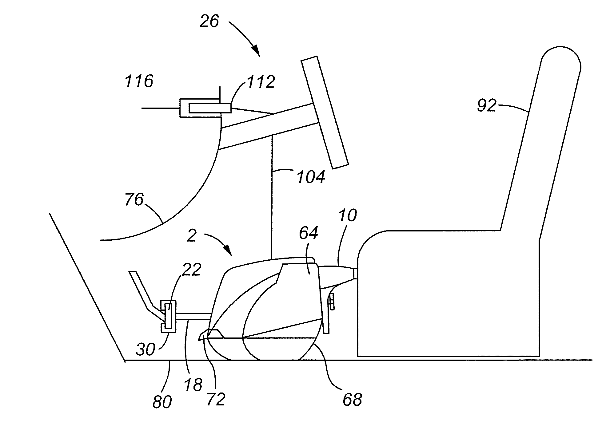
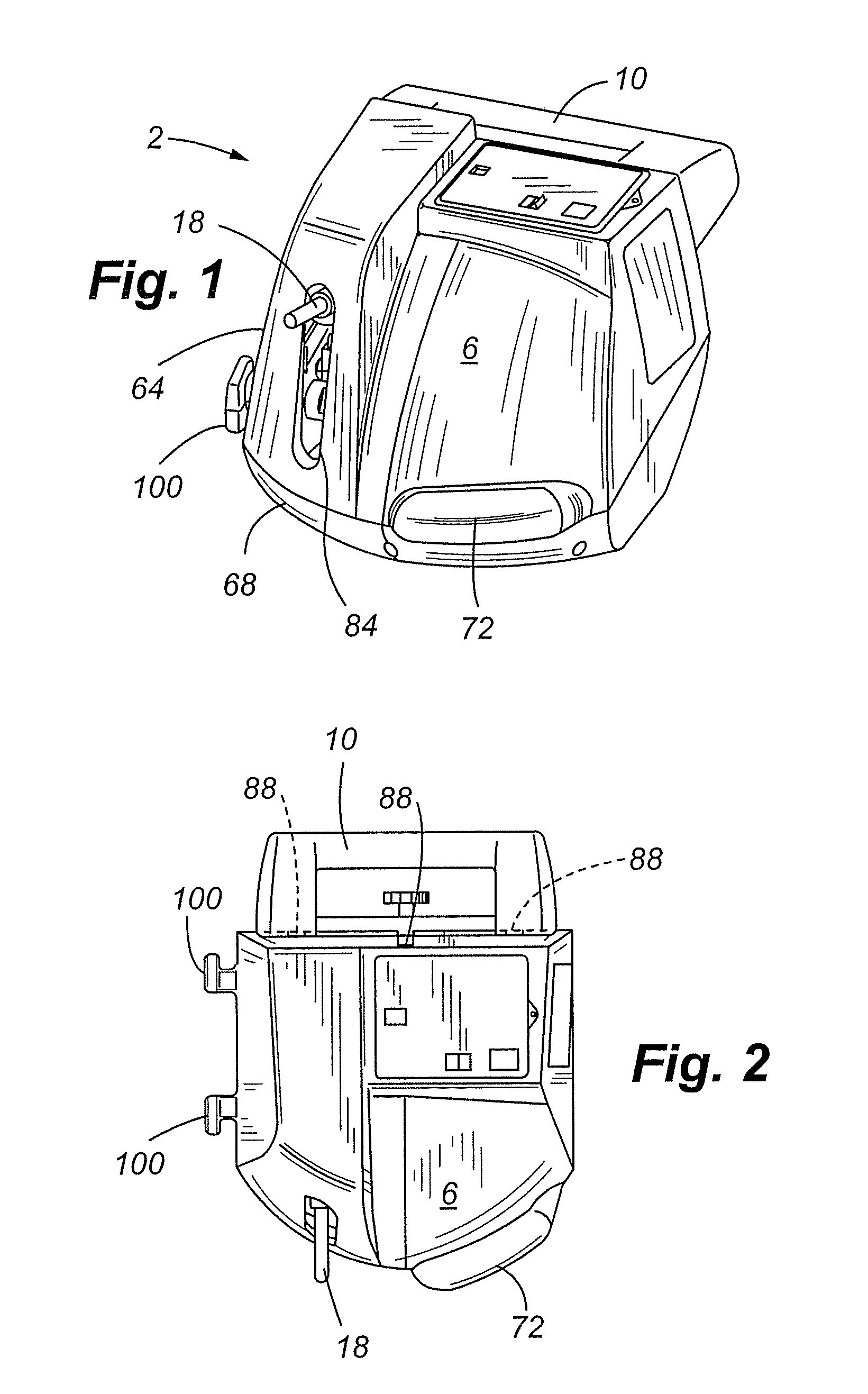
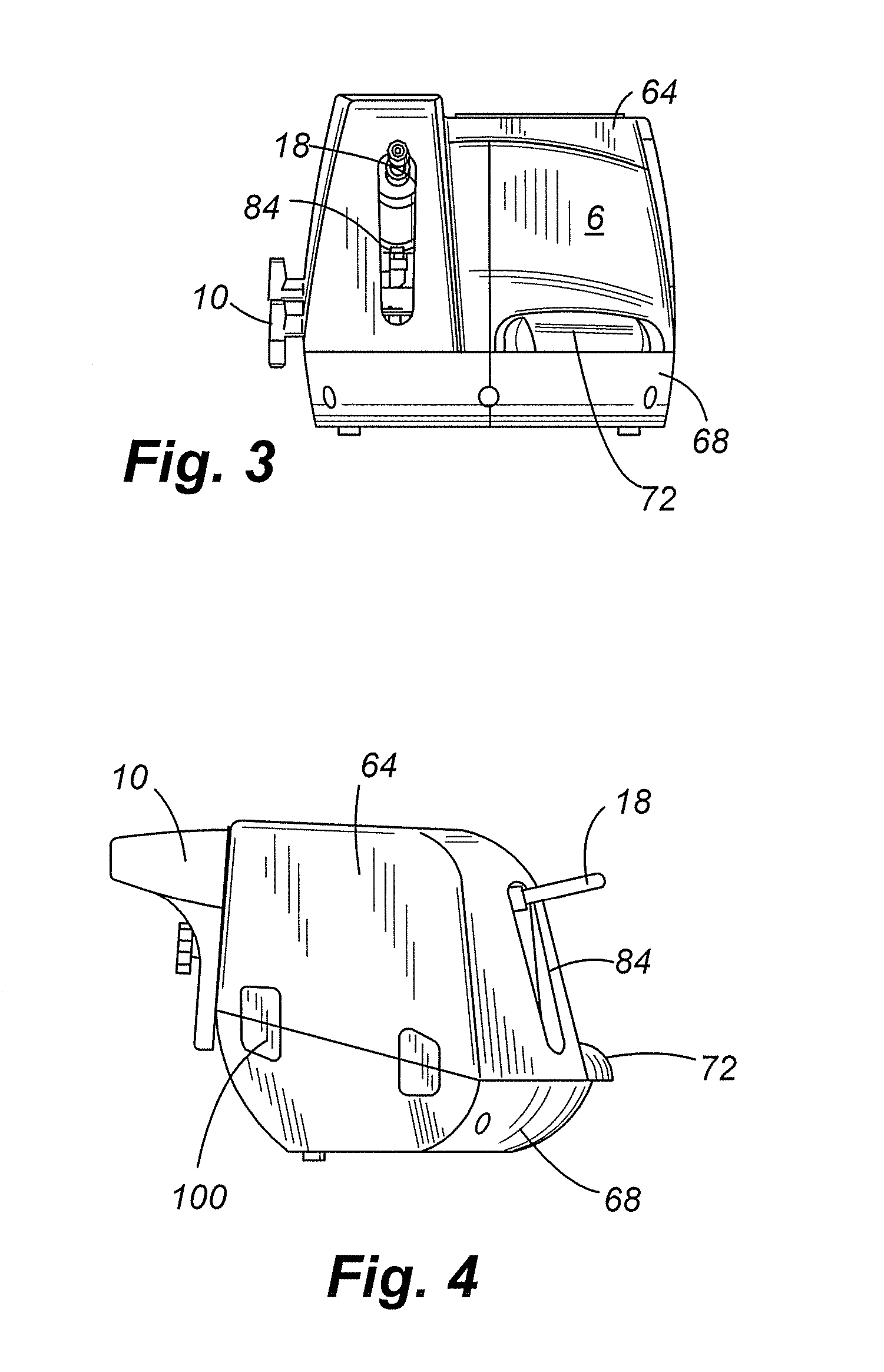
[0046]FIGS. 1-14 depict various perspective and elevation views of one embodiment of the auxiliary braking apparatus 2. In general, the auxiliary braking apparatus 2 is comprised of a housing 6 interconnected to a stand-off member 10. As shown in FIG. 10, a basic schematic representation of one embodiment of the present invention, the housing 6 encases a cylinder 14 with an actuator arm 18 that...


PUM


Abstract

An auxiliary braking system and method of controlling the braking a towed vehicle is provided that includes a remote control that is in selective communication with an auxiliary braking unit positioned in a towing vehicle. More specifically, it is often desirable for the operator of the towing vehicle to assess the performance of the auxiliary braking apparatus positioned in a towed vehicle. In addition, it is often advantageous for the operator to perform real time adjustments to the performance parameters of the auxiliary braking apparatus positioned in the towing vehicle without having to cease driving and physically access the auxiliary braking device.

Description

CROSS REFERENCE TO RELATED APPLICATION [0001] This application claims the benefit of U.S. Provisional Patent Application Ser. No. 60 / 739,376, filed Nov. 23, 2005, which is incorporated by reference in its entirety herein. This application is also related to U.S. patent application Ser. No. 10 / 015,339, now U.S. Pat. No. 6,634,466, filed Dec. 12, 2001; U.S. patent application Ser. No. 10 / 295,967, now abandoned, filed Nov. 15, 2002; U.S. patent application Ser. No. 10 / 650,347, now U.S. Pat. No. 6,918,466, filed Aug. 27, 2003; U.S. patent application Ser. No. 29 / 185,671, now U.S. Patent No. D498,190, filed Jun. 30, 2003; U.S. patent application Ser. No. 29 / 166,507, now U.S. Patent No. D477,553, filed Aug. 27, 2002; U.S. patent application Ser. No. 10 / 739,491, now abandoned, filed Dec. 17, 2003; and U.S. patent application Ser. No. 29 / 243,369, filed Nov. 23, 2005, all of which are incorporated by reference in their entireties herein.FIELD OF THE INVENTION [0002] The present invention rel...

Claims


Application Information

Patent Timeline
Patent Type & Authority Applications(United States)
IPC IPC(8): B60T13/00
CPCB60T7/06Y10T74/20B60T7/20B60T13/746
Inventor KAMINSKI, GARYSICKLER, VICKIGRAY, JONATHAN
Owner HOPKINS MFG
Why Eureka
Try Eureka