Method and apparatus for controlling the speed of a DC motor

a dc motor and speed control technology, applied in the direction of motor/generator/converter stopper, dynamo-electric converter control, dc motor rotation control, etc., can solve the problems of increasing the temperature of power devices, and affecting the operation of motors

Active Publication Date: 2007-05-24
COMAIR ROTRON US LLC
View PDF3 Cites 4 Cited by
  • Summary
  • Abstract
  • Description
  • Claims
  • Application Information

AI Technical Summary

Benefits of technology

[0006] In some embodiments, the motor would attain a maximum speed if the duration of the on cycle of the commutation signal were not varied. This desired speed may be less than the maximum speed. The amplitude of the modified commutation signal illustratively is greater than zero. Among other things, the method and apparatus also may forward the modified commutation signal to the stator. In some embodiments, the commutation signal controls current draw by the motor.

Problems solved by technology

Undesirably, this can create electromagnetic interference (EMI), which is known to 1) interfere with other electronic devices, and 2) increase the temperature of power devices.
Such additional devices, however, generally increase the cost and power consumption of the motors.

Method used


Image

  • Method and apparatus for controlling the speed of a DC motor
  • Method and apparatus for controlling the speed of a DC motor
  • Method and apparatus for controlling the speed of a DC motor

Examples


Embodiment Construction

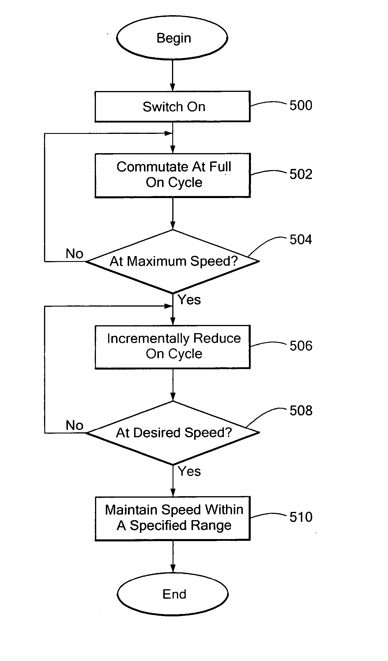
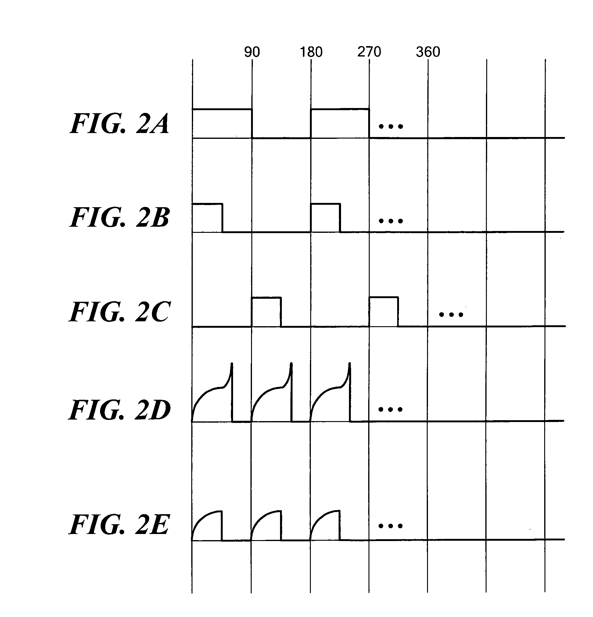
[0022] Rather than use pulse width modulated techniques, illustrative embodiments of the invention control rotor speed by producing one or more reduced duty cycle motor commutation signals. Various embodiments therefore do not require high frequency filtering circuitry for removing electromagnetic interference produced by pulse width modulation processes. Details of various embodiments are discussed below.

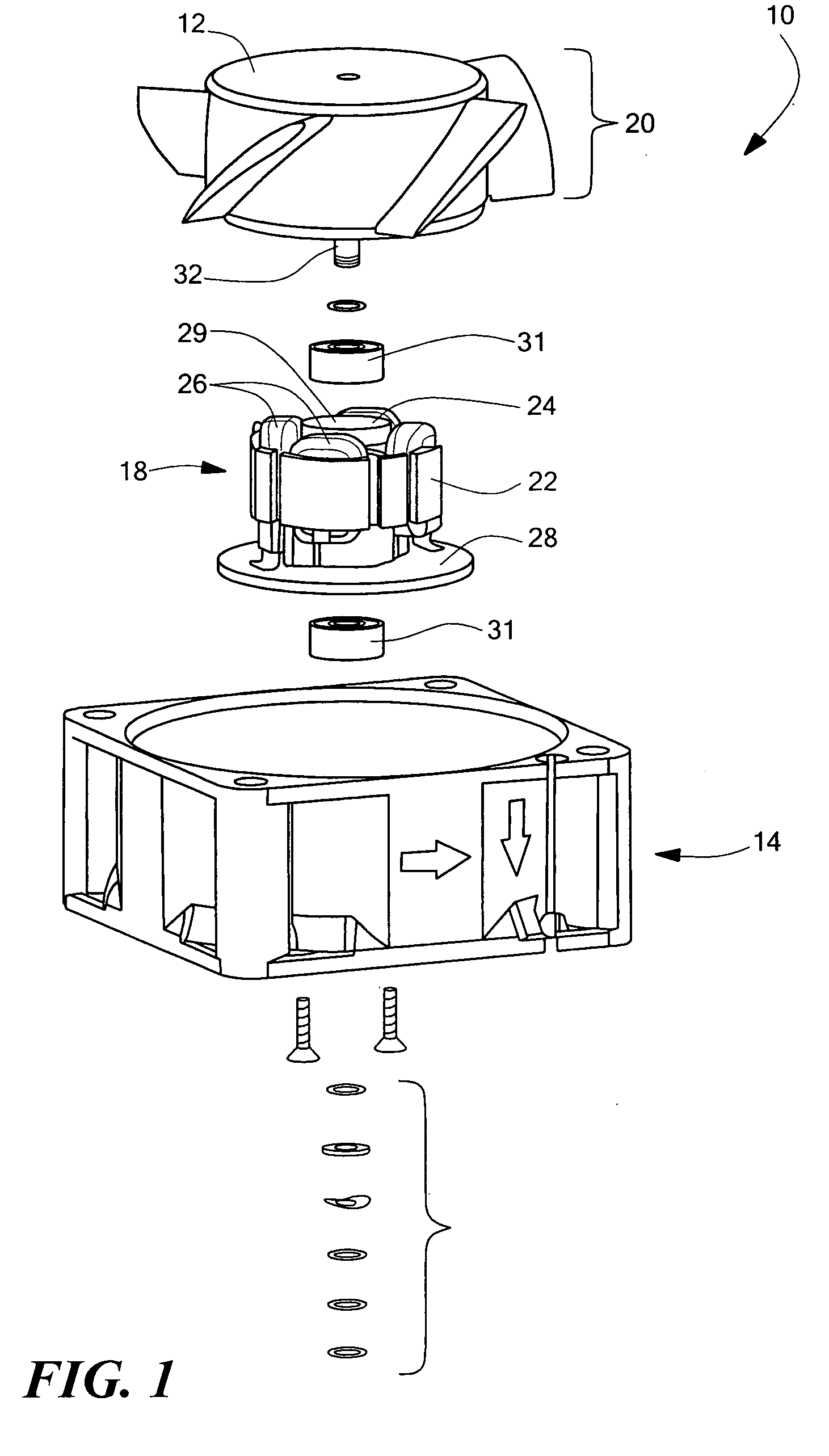
[0023]FIG. 1 schematically shows an exemplary brushless, four pole, DC motor 10 that may implement illustrative embodiments of the invention. In particular, the motor 10 includes a propeller 12 and thus, is a part of a cooling fan. To that end, the motor 10 includes a housing 14 with venturi (not shown), a stator portion 18 secured to the housing 14, and a rotor 20, which includes the propeller 12. It should be noted that although the motor 10 is implemented as a fan, illustrative embodiments apply to other motor applications. Accordingly, description of the motor 10 as a fan is b...


PUM


Abstract

A method and apparatus for controlling the speed of a DC electric motor receives a periodic commutation signal having a fixed duration on cycle and an off cycle. The commutation signal then is modified to form a periodic modified commutation signal having substantially the same period duration as the commutation signal. The modified commutation signal has a single on cycle per period. The method and apparatus then determine a desired speed of the motor, and vary the duration of the on cycle of the commutation signal to form the on cycle of the modified commutation signal. The on cycle of the modified commutation signal has a duration that is less than the fixed duration. By varying in this manner, the rotor rotates at substantially the desired speed.

Description

FIELD OF THE INVENTION [0001] The invention generally relates to motors and, more particularly, the invention relates to electric motors. BACKGROUND OF THE INVENTION [0002] Electric motors typically have a stationary portion (“stator”) that energizes a rotational portion (“rotor”) by means of a prescribed signal. For example, DC electric motors typically generate a signal (“commutation signal”) that causes the stator to produce an alternating magnetic field. This magnetic field interacts with permanent magnets in the rotor to cause the rotor to rotate in a controlled manner. [0003] To that end, the commutation signal typically is a periodic signal having a single “on” portion (i.e., the signal is non-zero) and a single “off” portion (i.e., the signal is zero) for every period of the signal. To vary the speed of the rotor, many motors pulse width modulate the on portion of the commutation signal. For example, to reduce the speed by twenty percent from a maximum speed, a prior art mot...

Claims


Application Information

Patent Timeline
Patent Type & Authority Applications(United States)
IPC IPC(8): H02P7/00
CPCH02P7/0044H02P7/04
Inventor ECHAZARRETA, JAIME
Owner COMAIR ROTRON US LLC
Why Eureka
Try Eureka