Automatic exposure control method and automatic exposure compensation apparatus

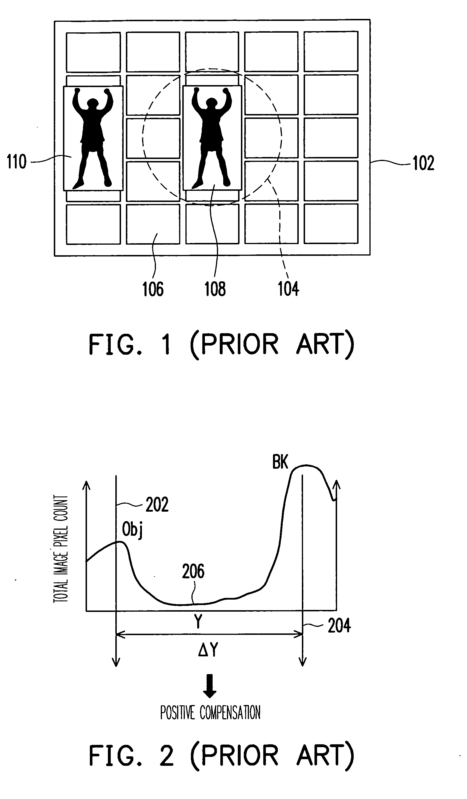
an exposure compensation and automatic technology, applied in the direction of color television details, television system details, television systems, etc., can solve the problem of described misjudgment of an image frame of a scene, excessively bright or dark principal object frames,

Active Publication Date: 2007-05-24
ICATCH TECH INC
View PDF6 Cites 43 Cited by
  • Summary
  • Abstract
  • Description
  • Claims
  • Application Information

AI Technical Summary

Benefits of technology

[0013] From the aforementioned, it is clear that the present invention uses a image analysis algorithm to properly define the exposure value (EV) corresponding appropriately to each scene. Since a variety of typical conditions encountered in a photographic scene, such as high-lighting scene, normal front-lighting, back-lighting, strong back-lighting, strong front-lighting, and dark scene are considered and included in a plurality of sub-ranges in the established coordinate system. Furthermore, each captured

Problems solved by technology

Since the direction and intensity of a light source for a photographic scene is varied, an excessively bright or dark principal object frame is as a result.
However, a general-purpose light-metering method is not capable of effectively alleviating the problem.
Since the background is a brighter region (for example, the background is the sky), the sky would be misjudged to be the principal object to have excessive luminance and an incorrect negative compensation, i.e. a deducted lighting, would be performed, which leads to the above-described misjudgement of an image frame of a scene.
However, the aforementioned method would still fail to provide a correct judgment when a principal object is under strong front lighting. FI

Method used


Image

  • Automatic exposure control method and automatic exposure compensation apparatus
  • Automatic exposure control method and automatic exposure compensation apparatus
  • Automatic exposure control method and automatic exposure compensation apparatus

Examples


Embodiment Construction

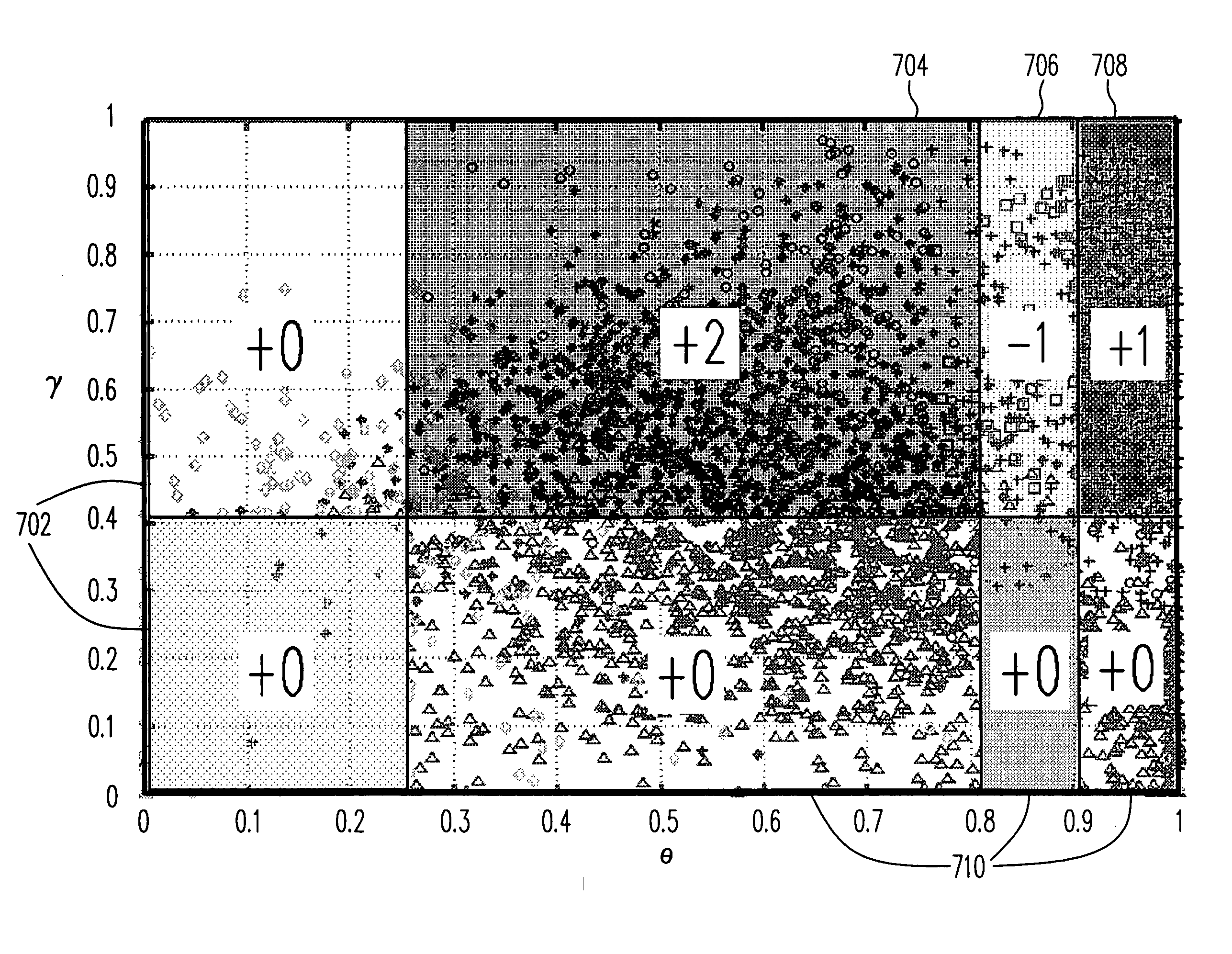
[0030] To reduce the chance of misjudgement with exposure in the scene and to assure every scene to obtain proper exposure compensation, the present invention provides an automatic exposure control method different from the prior art. The method is explained by means of the disclosed embodiments together with the accompanying drawings as follows.

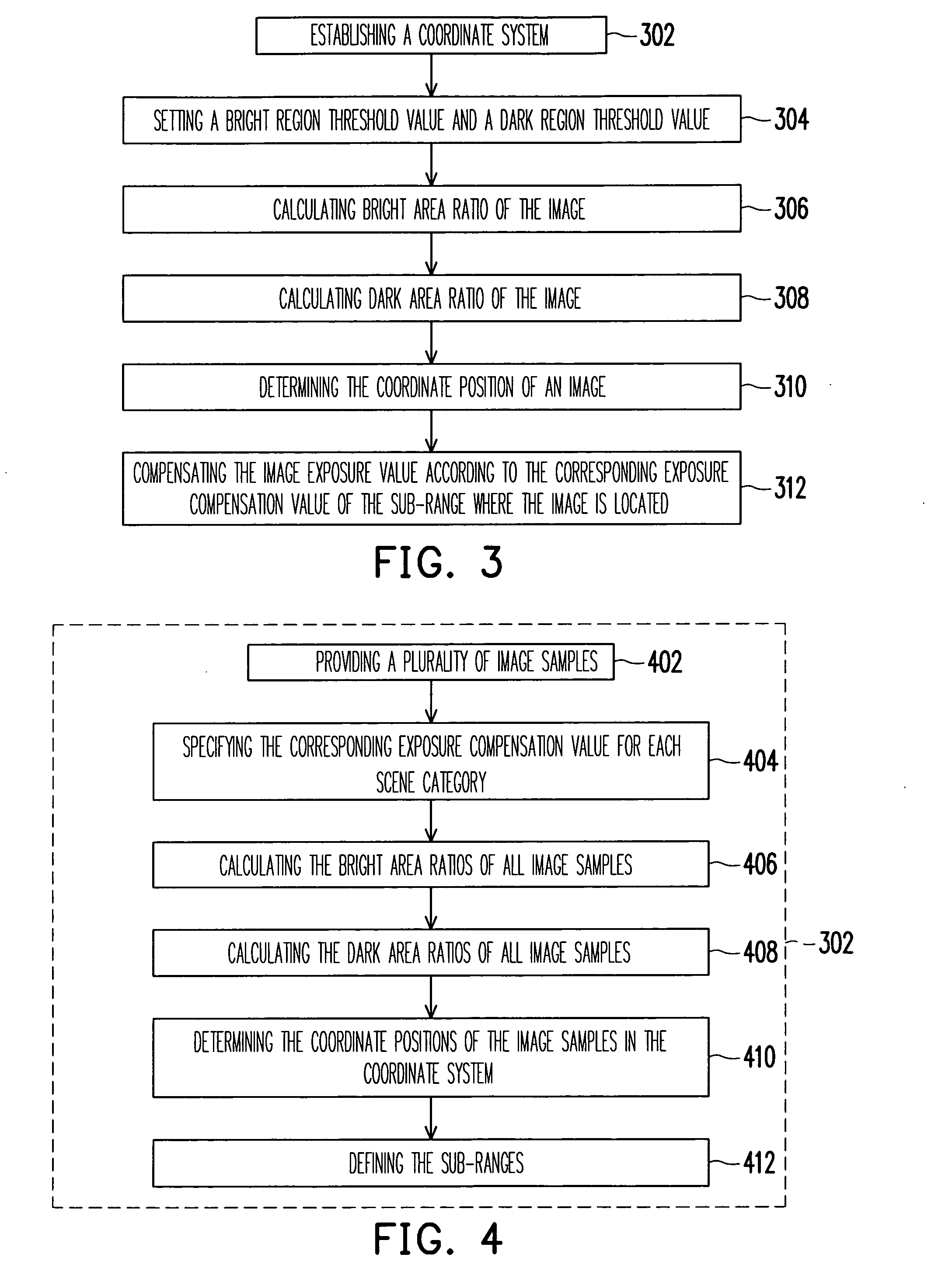
[0031]FIG. 3 is a flowchart of an automatic exposure control method according to an embodiment of the present invention. Referring to FIG. 3, six steps are included, which include a plurality of steps 302, 304, 306, 308, 310 and 312. In which, step 302 is to establish a coordinate system. Referring to FIG. 4, a flowchart for establishing a coordinate system according to an embodiment of the present invention is illustrated.

[0032] Six sub-steps in total are included for step 302, which are a plurality of sub-steps 402, 404, 406, 408, 410 and 412, as shown in FIG. 4. First, at the sub-step 402, a plurality of image samples are provided. Next...


PUM


Abstract

An automatic exposure control method and compensation apparatus are disclosed. It includes a coordinate system having sub-ranges with different corresponding exposure compensation values. It includes the setting of bright and dark regions threshold values and the calculation of the ratios of the pixel count in an image where the luminance of each pixel is higher than the bright area threshold value for obtaining a bright area ratio, and also includes the calculation of the ratio of the pixel count in an image where the luminance of each pixel is lower than the dark area threshold value for obtaining a dark area ratio. Afterwards, the image position in the coordinate system is determined. When the image position in the coordinate system is fallen inside one of the sub-ranges, the corresponding exposure compensation value of the sub-range where the image is located is given to compensate the exposure value of the image.

Description

CROSS-REFERENCE TO RELATED APPLICATION [0001] This application claims the priority benefit of Taiwan application serial no. 94141251, filed on Nov. 24, 2005. All disclosure of the Taiwan application is incorporated herein by reference. BACKGROUND OF THE INVENTION [0002] 1. Field of Invention [0003] The present invention relates to an automatic exposure control method and an automatic exposure compensation apparatus, and particularly to an automatic exposure control method and an automatic exposure compensation apparatus used for setting the exposure compensation value of an image. [0004] 2. Description of the Related Art [0005] The components of a color image processing system mainly include an image acquisition unit, an image regression and processing unit, an image display unit, and an image compression unit. In which, the image acquisition unit is formed by an image sensor, which is a two-dimensional array device formed by a plurality of photo-diodes and which converts a detected...

Claims


Application Information

Patent Timeline
IPC IPC(8): H04N5/235
CPCH04N5/2351H04N23/71
Inventor WU, CHENG-YULIN, ZHE-HONGCHEN, HUNG-REN
Owner ICATCH TECH INC
Why Eureka
Try Eureka