
Multi-cavity fabry-perot interferometric thin-film sensor with built-in temperature compensation

a thin-film sensor, interferometer technology, applied in the field of fiber optic sensors, can solve problems such as source of error, use of such labels, and compromise both sensitivity and specificity of the sensor

Inactive Publication Date: 2007-05-24
VIRGINIA TECH INTPROP INC
View PDF6 Cites 12 Cited by
  • Summary
  • Abstract
  • Description
  • Claims
  • Application Information

AI Technical Summary

Benefits of technology

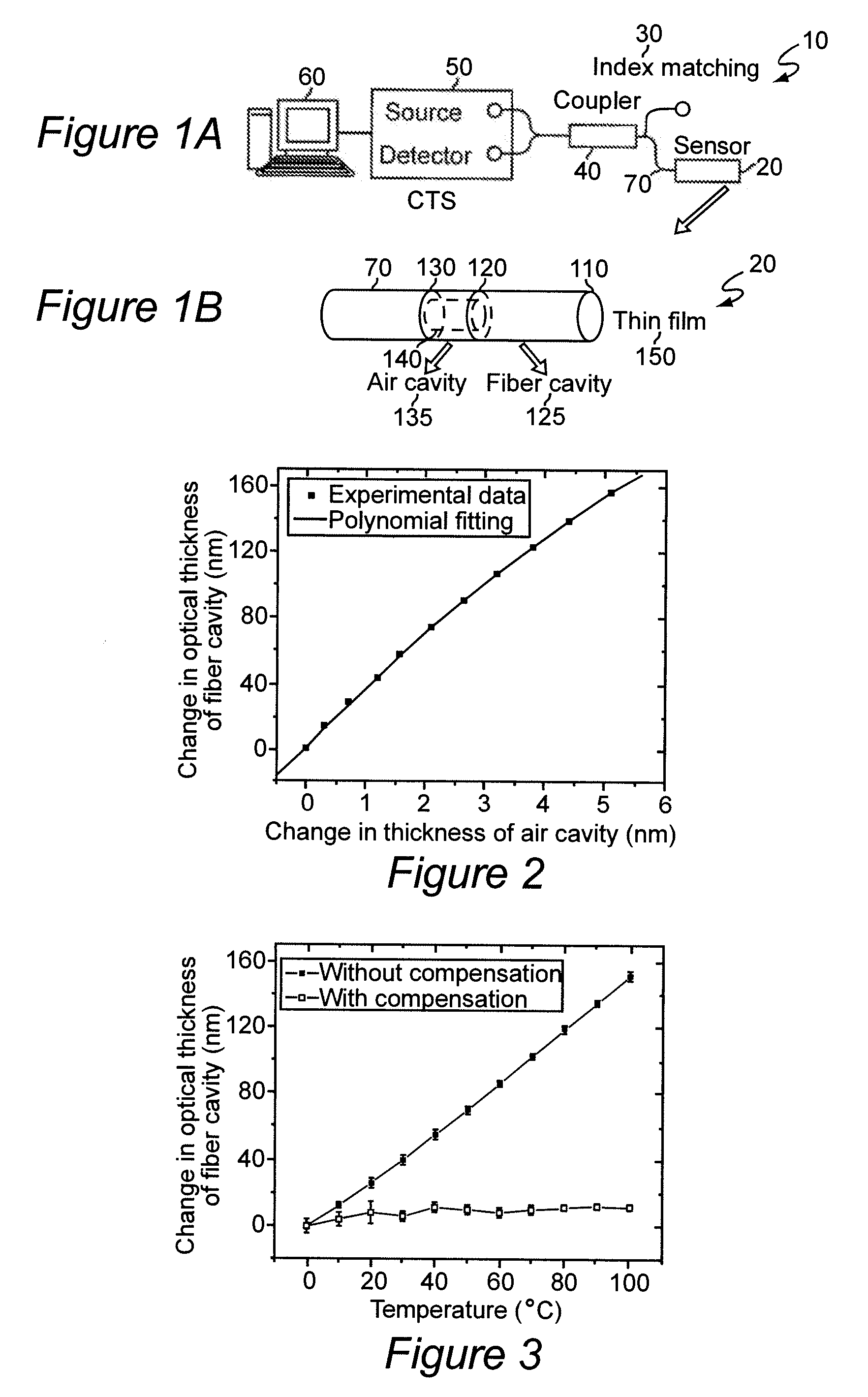
[0009] In order to accomplish these and other objects of the invention, a multi-cavity Fabry-Perot (FP) structure is provided in the fiber-optic structure forming the thin-film sensor. Such a multi-cavity FP structure has at least three reflecting surfaces and can be arranged such that the dimensions of the cavities and thus the distance between reflecting surfaces will vary with temperature while one of the surfaces at the end of the fiber-optic element can have a thin film formed thereon in accordance with a material or parameter of interest. The temperature compensation capability can be enhanced by selection of different cavity materials and may preferably be applied by extraction of temperature information from the cavities multiplexed (e.g. by time or wavelength) with extracting of information from the thin film or calibrating the sensor in regard to temperature using a separate sensor.

Problems solved by technology

By the same token, however, these mechanisms providing high sensitivity to the optical thickness of thin films (which also makes such sensors useful for the study of the thin films themselves) also provide high sensitivity to temperature changes which may be useful for temperature measurements but may be a source of error for other parameters of interest such as the presence of particular materials.
The existence of such a potential source of error compromises both sensitivity and specificity of the sensor and, indeed, it has been necessary in some applications to increase the concentration of a material for it to be reliably detected.
However, the use of such labels may interfere with a process being monitored, such as the evolution of a material during a chemical reaction, in ways which may not be predictable and, in any event, detection of a label, at best, provides only an indirect measurement of the parameter of interest.

Method used


Image

  • Multi-cavity fabry-perot interferometric thin-film sensor with built-in temperature compensation
  • Multi-cavity fabry-perot interferometric thin-film sensor with built-in temperature compensation
  • Multi-cavity fabry-perot interferometric thin-film sensor with built-in temperature compensation

Examples


Embodiment Construction

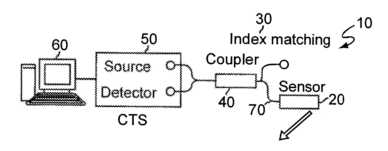
[0015] Referring now to the drawings, and more particularly to FIGS. 1A and 1B, there is schematically shown a multi-cavity Fabry-Perot interferometric (MFPI) sensor in accordance with a preferred embodiment of the invention. The MFPI sensor is distinguished by its simplicity, small size, high sensitivity, low cost and capability of measurement of ultra-thin films. Such thin films are normally characterized by x-ray scattering, near-field scanning optical microscopy, atomic force microscopy and other complex and costly laboratory techniques. However, since the changes in optical cavity length induced by the thermo-optic effect and thermal expansion have significant influence on measurement accuracy using MFPI sensors, it is necessary to introduce temperature compensation in order to perform high accuracy measurements at varying temperatures. The overall system shown in FIG. 1A is similar to some known systems and preferably includes a MFPI sensor 20, significant details of which are...


PUM

PropertyMeasurementUnit
optical thicknessaaaaaaaaaa
temperatureaaaaaaaaaa
optical thicknessaaaaaaaaaa

Abstract

A fiber optic sensor includes at least two Fabry-Perot (FP cavities) defined by at least three partially reflecting surfaces which individually and together are capable of generating different interference spectra which are affected by temperature. One of the FP cavities is formed at an end of the sensor and includes a surface which is capable of supporting a thin film, the optical thickness of which is to be measured. The other FP cavity between the lead-in fiber and the first FP cavity thus does not include the film and can thus independently provide highly accurate temperature information for calibrating the optical length of the second FP cavity and compensation for temperature effects on measurement of the thin film supported thereon, preferably by subtraction of a calibrated temperature-dependent change in optical length of the second FP cavity from the measurement made.

Description

CROSS-REFERENCE TO RELATED APPLICATIONS [0001] This application claims benefit of priority of U.S. Provisional Patent Application Ser. No. 60 / 739,008, filed Nov. 23, 2005, which is hereby fully incorporated by reference.BACKGROUND OF THE INVENTION [0002] 1. Field of the Invention [0003] The present invention generally relates to fiber optic sensors and, more particularly, to temperature compensation of fiber optic sensors employing self-assembled thin films. [0004] 2. Description of the Prior Art [0005] There has been much recent interest in fiber-optic devices using so-called self-assembled multi-layer thin films. These sensors using self-assembled multi-layer thin films function by reflecting or scattering light to the cladding which is formed of the self-assembled thin films (which are easily and rapidly formed with excellent uniformity and repeatability by alternate immersion in any of a wide variety of cationic and anionic solutions at room temperature) and sensing is accomplis...

Claims


Application Information

Patent Timeline
Patent Type & Authority Applications(United States)
IPC IPC(8): G01B9/02G01B11/02G01B11/28
CPCG01N21/39G01N21/45G01N21/7746G01N2021/7773G01N2021/7779G01B11/0675G01B2290/25
Inventor ZHANG, YANCOOPER, KRISTIE L.WANG, ANBO
Owner VIRGINIA TECH INTPROP INC
Learn More