Switching circuit, and a modulator, demodulator or mixer including such a circuit

Active Publication Date: 2007-05-24
MEDIATEK INC
View PDF10 Cites 24 Cited by
  • Summary
  • Abstract
  • Description
  • Claims
  • Application Information

AI Technical Summary

Benefits of technology

[0005] It is thus possible to use such a switching circuit to improve noise performance of, for example a modulator by ensuring that the first and second steering switches, which may be implemented as first and second switching transistors switch during a time when they are not carrying current. This in turn reduces the effect of jitter in the signals which control the steering switches, and thereby enables more buffer circuits to be used

Problems solved by technology

It works well but exhibits significant output noise which tends to become exacerbated when trying to run at in

Method used


Image

  • Switching circuit, and a modulator, demodulator or mixer including such a circuit
  • Switching circuit, and a modulator, demodulator or mixer including such a circuit
  • Switching circuit, and a modulator, demodulator or mixer including such a circuit

Examples


Example

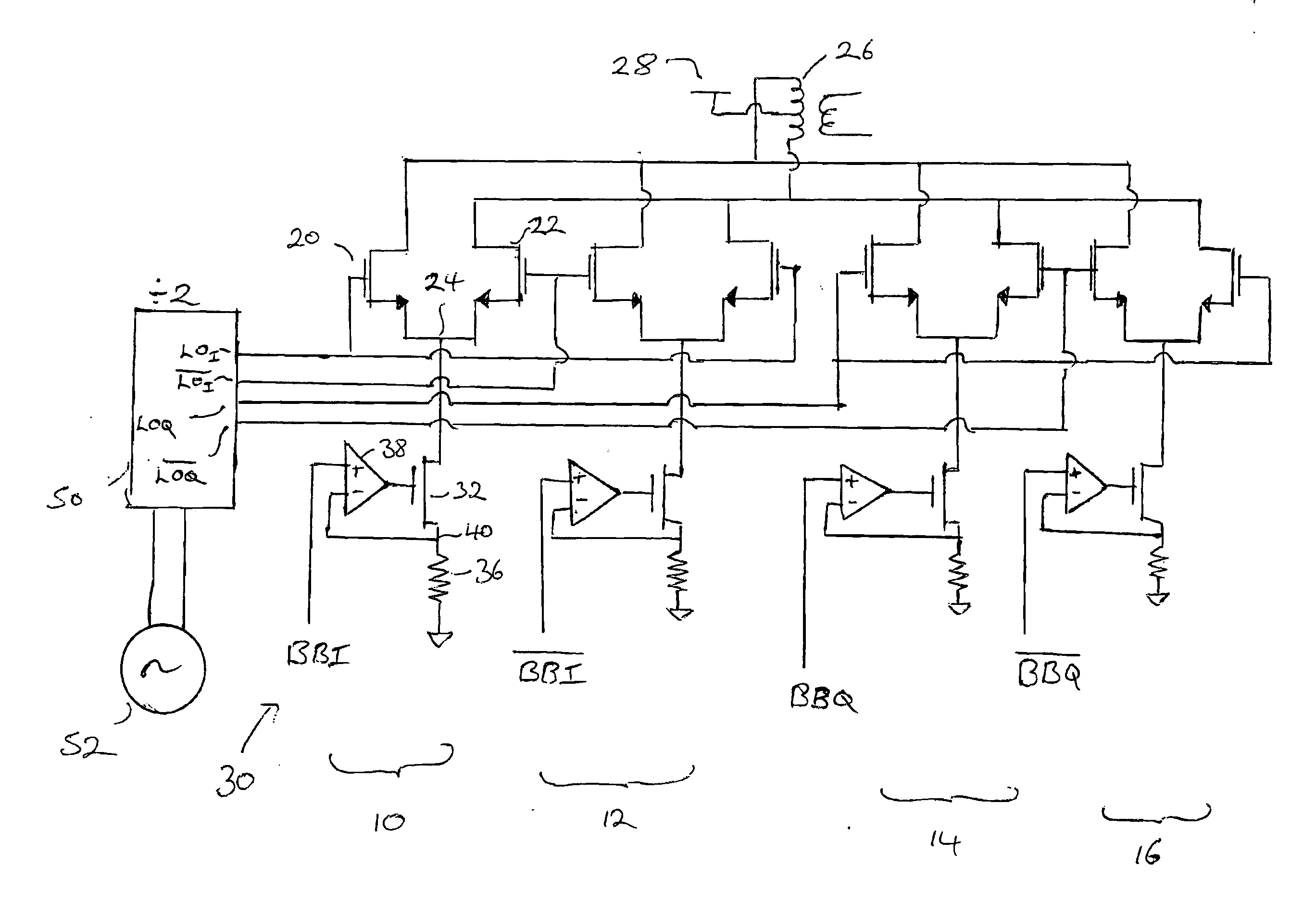
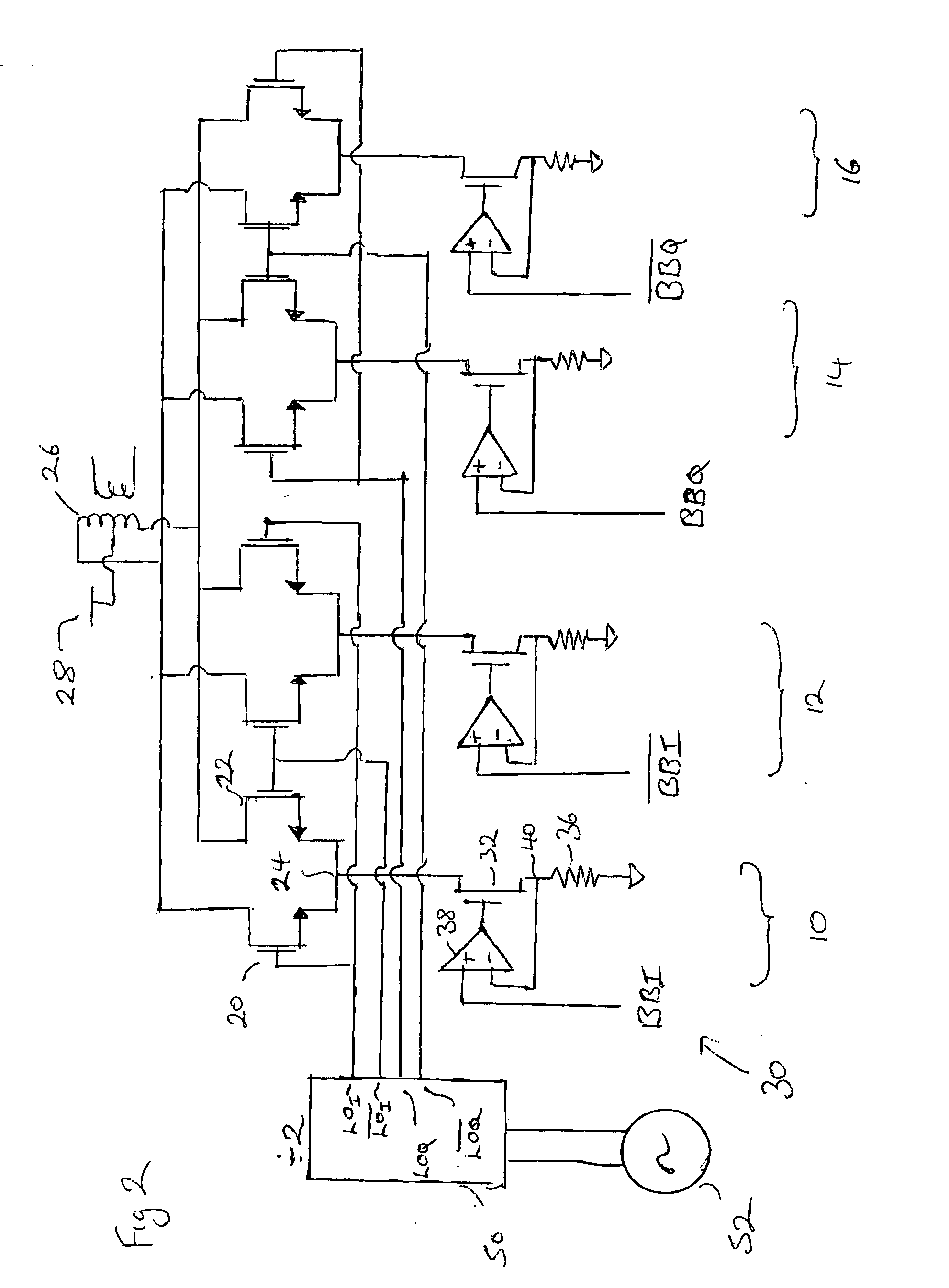
[0054] It is worth considering how the prior art modulator operates in order to understand its limitations. The prior art modulator of FIG. 2 comprises four individual modulator switching circuits 10, 12, 14 and 16 which are identical. Therefore only the first switching circuit 10 need be described in detail. The first switching circuit 10 comprises first and second switching transistors 20 and 22 connected in a “long tailed pair” configuration. Thus the source of the first transistor 20 and the source of the second transistor 22 are connected to a common node 24. The drain of the first transistor 20 is connected to a first end of a centre tapped coil 26 whereas the drain of the transistor 22 is connected to the second end of the second tapped coil 26. The centre tap of the coil 26 is connected to a supply rail 28. The common node 24 receives a current representative of a base band signal that is to be modulated. The current may be produced by a voltage to current converter, general...


PUM


Abstract

A switching circuit comprising: first and second steering switches operable to make or break a path between first and second terminals thereof, and each steering switch further having a control terminal for controlling the switch, the first and second steering switches having their control terminals driven by first and second switching signals, the first and second switching signals having a first frequency and the second switching signal being in anti-phase with the first switching signal and a first chopping switch operable to make or break a path between first and second terminals thereof and being connected in series with at least one of the first and second steering switches and receiving at its first terminal an input to be modulated, wherein the control terminal of the chopping switch is driven by a first switching control signal such that the chopping switch is non-conducting while the first and second steering switches are changing between being conducting and being non-conducting.

Description

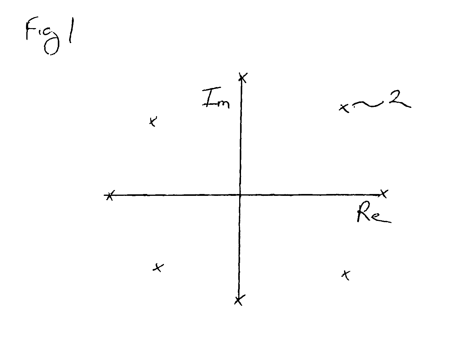
FIELD OF THE INVENTION [0001] The present invention relates to a switching circuit for use inside a modulator or a demodulator or mixer and to a modulator or a demodulator or mixer including such a circuit. BACKGROUND OF THE INVENTION [0002] Many transmission schemes encode data by modulating the amplitude and phase of a carrier so as to represent a symbol within a constellation diagram of the type shown in FIG. 1. The constellation diagram has axes extending in the real and the imaginary directions. The real and imaginary directions are orthogonal. In practical terms, if the real direction is represented by a sinusoid sin(ωt) then the imaginary is represented by sin⁡(ω⁢ ⁢t+π2)=cos⁡(ω⁢ ⁢t). Therefore an arbitrary symbol, such as that designated 2 can be represented by a suitable combination of the signals sin ωt and cos ωt. Modulators suitable for doing this are known as I-Q modulators and an example of such a modulator is shown in FIG. 2. It works well but exhibits significant out...

Claims


Application Information

Patent Timeline
IPC IPC(8): H04L12/56H04L12/28H04L27/36
CPCH03D7/1441H04L27/36H03D7/1458H03D7/165H03D2200/0084H03D2200/009
Inventor JONES, CHRISTOPHER GERAINT
Owner MEDIATEK INC
Why Eureka
Try Eureka