Imaging system

a technology of imaging system and imaging chamber, which is applied in the field of radiographic technology, can solve the problems of difficult rotation of containers or radiation sources, high cost of devices for ct system, and inability to meet the requirements of the moment, so as to achieve fast examination speed and no rotation

Active Publication Date: 2007-05-24
TSINGHUA UNIV +1
View PDF17 Cites 15 Cited by
  • Summary
  • Abstract
  • Description
  • Claims
  • Application Information

AI Technical Summary

Benefits of technology

[0008] In view of the above problems, the present invention is done. It is an object of the present invention to provide an imaging system using a straight-line trajectory which can obtain both a DR image and a tomographic image, and solve the problem of object overlapped problem in the perspective imaging so as to speedy achieve a stereoscopic radiography in the security inspection.
[0022] The imaging system according to the present invention achieves a real stereoscopic radiography by using a straight-line trajectory scan and reconstructing a tomographic or stereoscopic image through a straight-line filtered back-projection algorithm. The present imaging system has advantages of fast examination speed, no rotation, and out of problems such as large cone-angle problem in cone-beam CT systems. Therefore, the inventive imaging system may be potentially used in the fast security inspection field and large object inspection field.

Problems solved by technology

However, this requirement can hardly be satisfied currently even if a spiral CT with a large pitch is employed.
Further more, in regard to some large objects such as custom containers, it is very difficult to rotate the containers or the radiation source and the detectors.
Besides, the cost of devices for the CT system is quite high.
These above and other factors prevent the CT system from being widely used in the security inspection field.
However, compared with the CT systems, a radioscopic system has a drawback of no ability of avoiding an overlapping effect of objects in a radiation direction, and thus the inspection capability is restrained so that a real stereoscopic inspection and location can not be performed well.
However, it has a small range of the source coverage and reconstruction algorithms for tomosynthesis are used, which results in a poor capability of three-dimension imaging.

Method used


Image

  • Imaging system
  • Imaging system
  • Imaging system

Examples


first embodiment

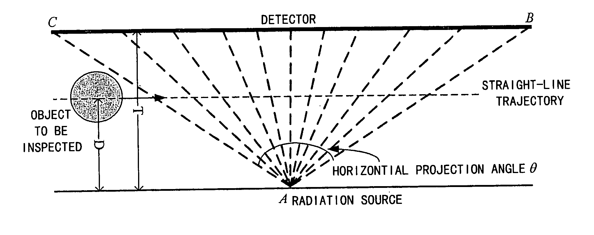
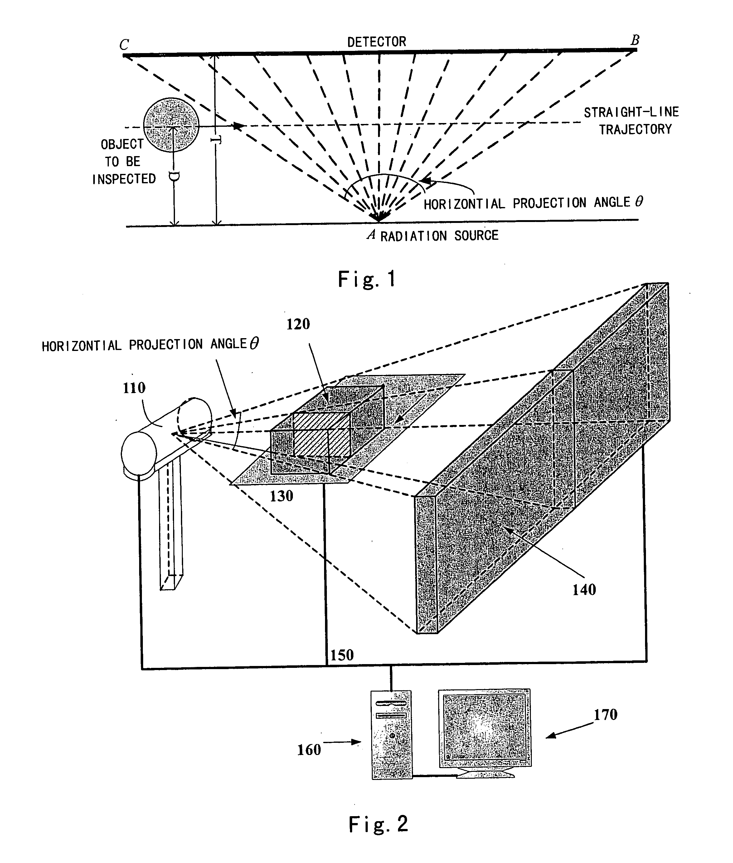
[0034]FIG. 1 is a plane diagram of straight-line trajectory scan performed in the imaging system according to the present invention. FIG. 2 is a structural diagram of the imaging system according to the first embodiment of the present invention.

[0035] As shown in FIG. 1, an object to be inspected moves between a radiation source A and a detector along a straight line. During the process of movement, the radiation source A emits radiations according to commands from a control system, which penetrates the object to be inspected. The detector receives transmitted signals, acquires projection data under the control of the control system, and stores the projection data into a memory.

[0036] The imaging system as shown in FIG. 2 comprises a radiation generating unit 110, a transporting unit 130, a data acquiring unit 140, a control and data signal bus 150, a controlling and image processing unit 160, and a display 170.

[0037] As shown in FIG. 2, the radiation generating unit 110 for exam...

second embodiment

[0081]FIG. 6 is a structural diagram of the imaging system according to the second embodiment of the present invention.

[0082] The imaging system according to the second embodiment of the present invention differs from the first embodiment in that another collinear detector array capable of moving up and down in the Z direction is further provided in a case where the detector array is of a single column (single slice, that is collinear array) so that a plurality of tomographic images can be obtained, and thus the stereoscopic imaging can be achieved with a small quantity of detector elements. Therefore, as compared with the first embodiment, the number of the detector elements in the detector array is dramatically decreased.

[0083] As shown in FIG. 6, the detector matrix in the data acquiring unit of the second embodiment includes two sets of single slice detector arrays 141 and 142 for acquiring the transmitted projection data of the cone-beam ray, one is horizontal, the other is v...


PUM

PropertyMeasurementUnit
projection anglesaaaaaaaaaa

Abstract

It is disclosed an imaging system comprising: radiation generating means including at least one radiation source for generating radiations; data acquiring means including an detector matrix faced the radiation source for obtaining projection data by receiving radiations penetrated through an object to be inspected; transporting means for making the object to be inspected between the radiation source and the detector matrix linearly moving relative to the radiation source and the detector matrix; and controlling and image processing means for controlling the radiation generating means, the data acquiring means and the transporting means, and for reconstructing an image of the object to be inspected from the projection data. The imaging system according to the present invention achieves a real stereoscopic radiography by using straight-line trajectory scan and reconstructing a tomographic or stereoscopic image through a straight-line filtered back-projection algorithm. The present imaging system has advantages of fast examination speed, no rotation, and out of large cone-angle problem in a circular-orbit cone-beam CT.

Description

BACKGROUND OF THE INVENTION [0001] 1. Field of the Invention [0002] The present invention relates to the radiographic technology, and more particularly to an imaging system using a straight-line trajectory scan to improve the speed of a radiographic security inspection. [0003] 2. Description of the Prior Art [0004] Security inspection is much more significant in anti-terrorism and anti-drug-smuggles. After 911, US makes more and more account of the security inspection in public places such as airports and railway stations. In addition, with the development of anti-drug-smuggles, the requirements for inspecting containers and luggage at Custom are increased. [0005] Current security inspection systems are mainly radiographic systems, and in the radiography field, radioscopic system such as DR (digital radiography) is commonly used, while stereo-imaging equipment such as CT (computed tomography) system is not widely employed. This is because a practical security inspection system gener...

Claims


Application Information

Patent Timeline
Patent Type & Authority Applications(United States)
IPC IPC(8): G01N23/04G03B42/02
CPCG01N23/04A61B6/027
Inventor CHEN, ZHIQIANGZHANG, LIGAO, HEWEIKANG, KEJUNCHENG, JIANPINGLI, YUANJINGLIU, YINONGXING, YUXIANGZHAO, ZIRANXIAO, YONGSHUN
Owner TSINGHUA UNIV
Why Eureka
Try Eureka