Fan and air conditioner

a technology of fan and air conditioner, which is applied in the direction of domestic cooling apparatus, lighting and heating apparatus, heating types, etc., can solve the problems of unbalanced distribution of intake air flow, difficult to obtain uniform distribution, etc., and achieves the effect of improving facilitating guided, and maintaining the air blowing performance of centrifugal fans

Inactive Publication Date: 2007-05-24
DAIKIN IND LTD
View PDF4 Cites 17 Cited by
  • Summary
  • Abstract
  • Description
  • Claims
  • Application Information

AI Technical Summary

Benefits of technology

[0013] With this fan, at the circumferential portion of the scroll intake port, there is formed the bulged portion whose inner surface is formed evenly in the circumferential direction and whose outer surface portion far from the unit intake port bulges out to the side opposite the impeller. Consequently, it is possible to create, without changing the volume of the scroll casing, a condition that is similar to one in which the scroll intake port is disposed so as to incline to the unit intake port side, and the gas that is drawn in from the portion of the scroll intake port far from the unit intake port is easily guided. As a result, it is possible to improve the intake air distribution at the scroll intake port while maintaining the air blowing performance of the centrifugal fan, and it is thus possible to both improve the air blowing performance and reduce noise of the centrifugal fan and also the entire fan.
[0015] With this fan, the bulged portion is formed unevenly such that the bulging distance increases from the portion near the unit intake port to the portion far therefrom toward the side opposite the impeller. Consequently, it is possible to create a condition that is similar to one in which the scroll intake port is disposed so as to smoothly incline to the unit intake port side. As a result, it is possible to enhance the effect of improving the intake air distribution at the scroll intake port.
[0017] With this fan, the bulged portion is formed by the plurality of ribs that are provided at the circumferential portion of the scroll intake port so as to protrude to the side opposite the impeller. Consequently, it is possible to reduce the amount of materials to be used for the scroll casing, compared to the case where the bulged portion is formed as a solid bulged portion. Also, in the case where the scroll casing is formed as a resin molded product, it is possible to prevent the formation of a sink mark during molding. In addition, it is possible to improve the assemblability of the centrifugal fan and also the entire fan, compared to the case where the bulged portion is formed as a separate member.
[0019] With this air conditioner, the bulged portion provided at the circumferential portion of the scroll intake port is formed such that its inner surface is formed evenly in the circumferential direction and its outer surface portion far from the unit intake port bulges out to the side opposite the impeller. Consequently, it is possible to create, without changing the volume of the scroll casing, a condition that is similar to one in which the scroll intake port is disposed so as to incline to the unit intake port side, and the gas that is drawn in from the portion of the scroll intake port far from the unit intake port is easily guided. As a result, it is possible to improve the intake air distribution at the scroll intake port while maintaining the air blowing performance of the centrifugal fan, and it is thus possible to reduce noise and improve the air blowing performance of the centrifugal fan and also the entire air conditioner.

Problems solved by technology

Accordingly, in the case where the unit casing has the unit intake port that opens in the direction crossing the opening direction of the scroll intake port, when comparing the flow resistance of a portion of the scroll intake port near the unit intake port (here, lower portion of the scroll intake port) to the flow resistance of a portion of the scroll intake port far from the unit intake port (here, upper portion of the scroll intake port), the latter potion has a higher flow resistance; therefore the distribution of intake air flow (hereinafter referred to as the intake air distribution) becomes unbalanced, and a uniform distribution is difficult to obtain.
Such an unbalance of the intake air distribution is a cause of the increase in noise and the reduction of the air blowing performance.

Method used


Image

  • Fan and air conditioner
  • Fan and air conditioner
  • Fan and air conditioner

Examples


Embodiment Construction

[0045] A selected embodiment of a fan and an air conditioner according to the present invention will now be described with reference to the drawings.

(1) Structure of Air Conditioner

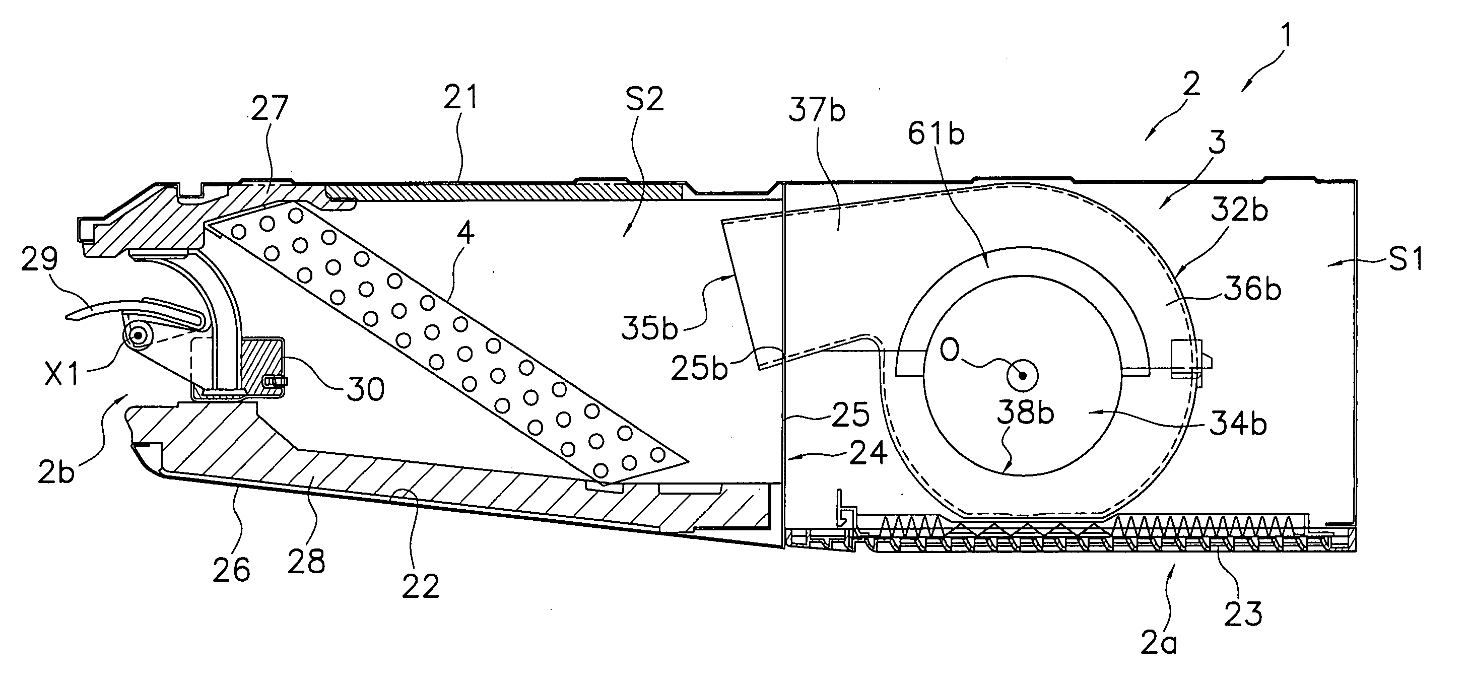
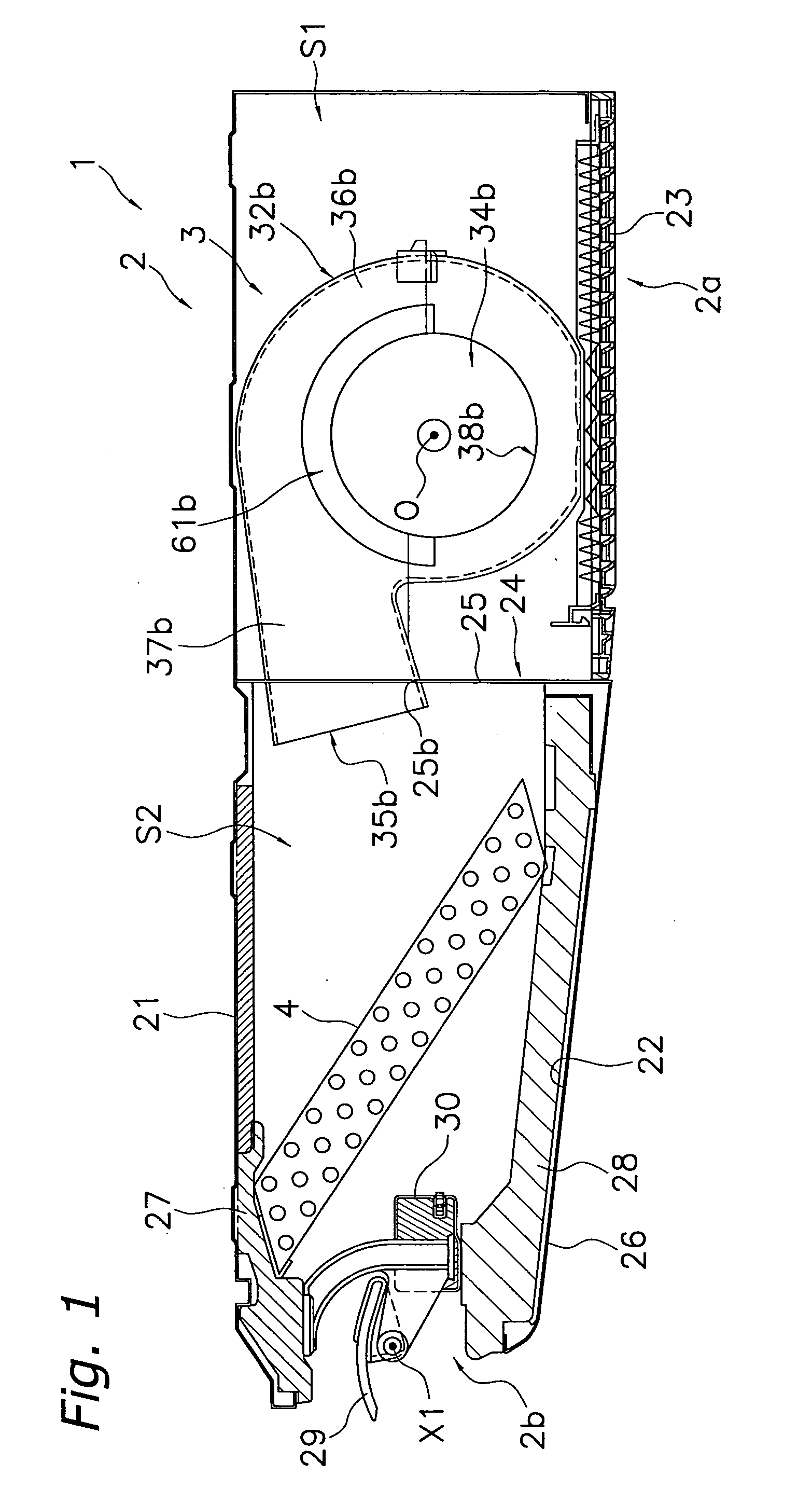
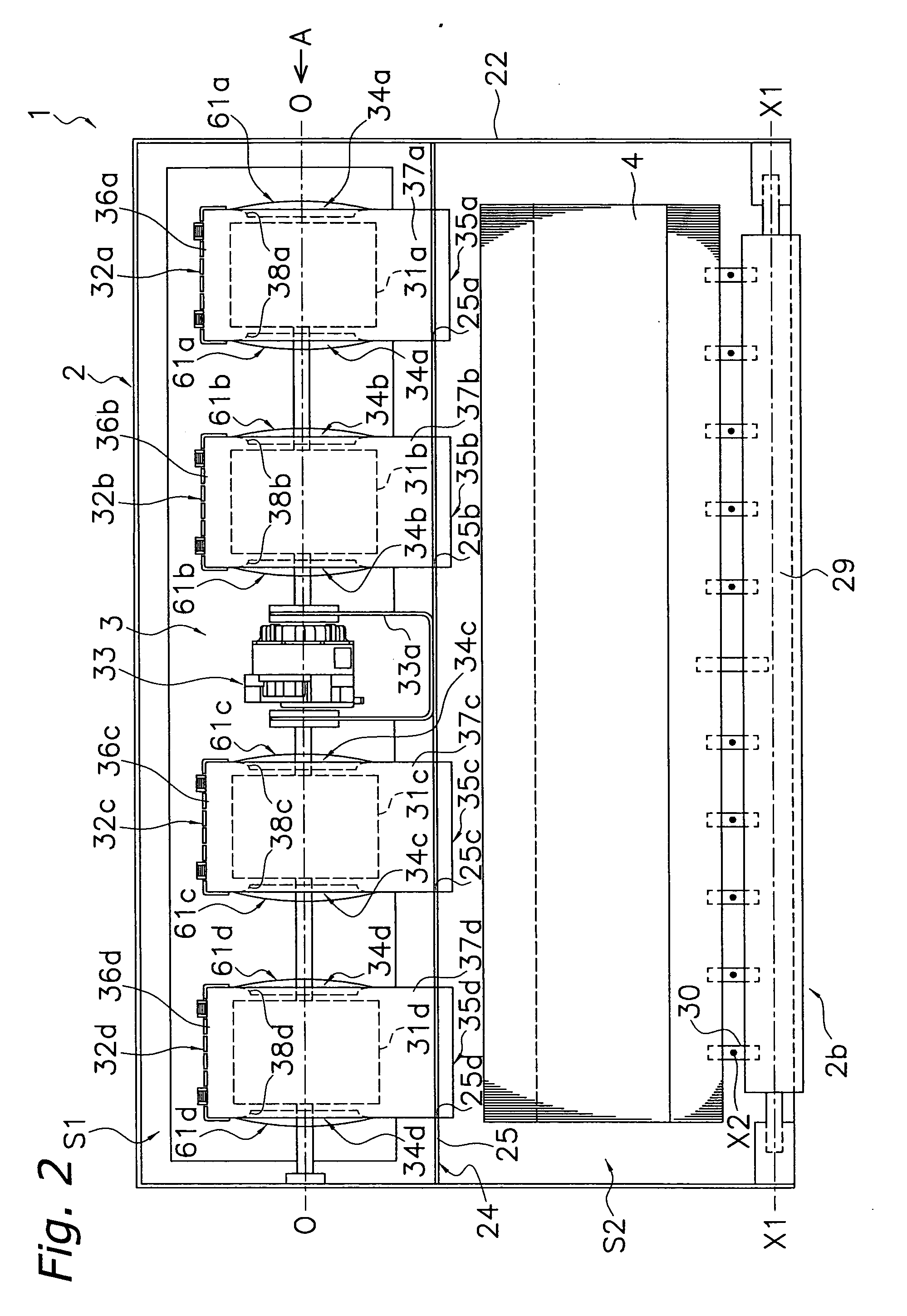
[0046]FIG. 1 and FIG. 2 show an air conditioner of a ceiling-hanging type as an embodiment of a fan and an air conditioner according to the present invention. Here, FIG. 1 shows a side cross sectional view of an air conditioner 1 (a cross sectional view to show a scroll casing 32b). FIG. 2 is a top view of the air conditioner 1 (with the top of a unit casing 2 removed).

[0047] This air conditioner 1 is placed such that it is hung from the ceiling of an air-conditioned room. The air condition 1 is connected to an outdoor unit (not shown) disposed outside via a refrigerant connecting pipe (not shown).

[0048] The air conditioner 1 mainly comprises the unit casing 2, a centrifugal fan 3, and a heat exchanger 4.

[0049] The unit casing 2 has a thin box shape that is long as a whole in a lateral direction, and...


PUM


Abstract

An air conditioner includes a centrifugal fan and a unit casing that houses the centrifugal fan. The centrifugal fan includes an impeller and a scroll casing that houses the impeller. The unit casing has a unit intake port that opens in a direction crossing an opening direction of a scroll intake port. At a circumferential portion of the scroll intake port of the scroll casing, there is formed a bulged portion with an inner surface that is formed evenly in a circumferential direction and an outer surface portion formed away from the unit intake port that bulges out to a side opposite the impeller.

Description

TECHNICAL FIELD [0001] The present invention relates to a fan and an air conditioner. More particularly, the present invention relates to a fan and an air conditioner, in which a centrifugal fan having an impeller and a scroll casing for housing the impeller is disposed inside a unit casing having a unit intake port that opens in a direction crossing an opening direction of a scroll intake port formed in the scroll casing, and in which gas is drawn into the scroll casing via the unit intake port of the unit casing. BACKGROUND ART [0002] Conventionally, there have been provided fans and air conditioners, in which a centrifugal fan having an impeller and a scroll casing for housing the impeller is disposed inside a unit casing, and in which gas is drawn into the scroll casing via a unit intake port of the unit casing. [0003] As an example of such fans and air conditioners, there is provided a ceiling-hanging type air conditioner. Such a ceiling-hanging type air conditioner mainly incl...

Claims


Application Information

Patent Timeline
Patent Type & Authority Applications(United States)
IPC IPC(8): F04D29/44F24F1/0083F24F13/08
CPCF04D29/4213F04D29/4226F24F1/0007F24F1/0033F24F2001/0037F24F1/0022F24F1/0047F24F1/0083F24F1/00F24F13/00
Inventor HIGASHIDA, MASAHITO
Owner DAIKIN IND LTD
Why Eureka
Try Eureka