Manufacture of fuel cell

a fuel cell and manufacturing technology, applied in the manufacture of cell components, sustainable manufacturing/processing, final product manufacturing, etc., can solve the problem of difficult positioning, and achieve the effect of reducing the feeding precision and efficiently manufacturing the fuel cell stack

Active Publication Date: 2007-05-24
NISSAN MOTOR CO LTD
View PDF6 Cites 44 Cited by
  • Summary
  • Abstract
  • Description
  • Claims
  • Application Information

AI Technical Summary

Benefits of technology

[0004] It is therefore an object of this invention to increase the feeding precision with which a polymer electrolyte membrane is fed from a roll so that the polymer electrolyte membrane

Problems solved by technology

However, taking roller slippage into con

Method used


Image

  • Manufacture of fuel cell
  • Manufacture of fuel cell
  • Manufacture of fuel cell

Examples


second embodiment

[0096] Next, referring to FIGS. 16A to 16C, this invention will be described.

[0097] In this embodiment, the separator 7 is formed on a conveyance film 95. The conveyance film 95 is formed with similar conveyance holes 10A to those formed in the MEA 1.

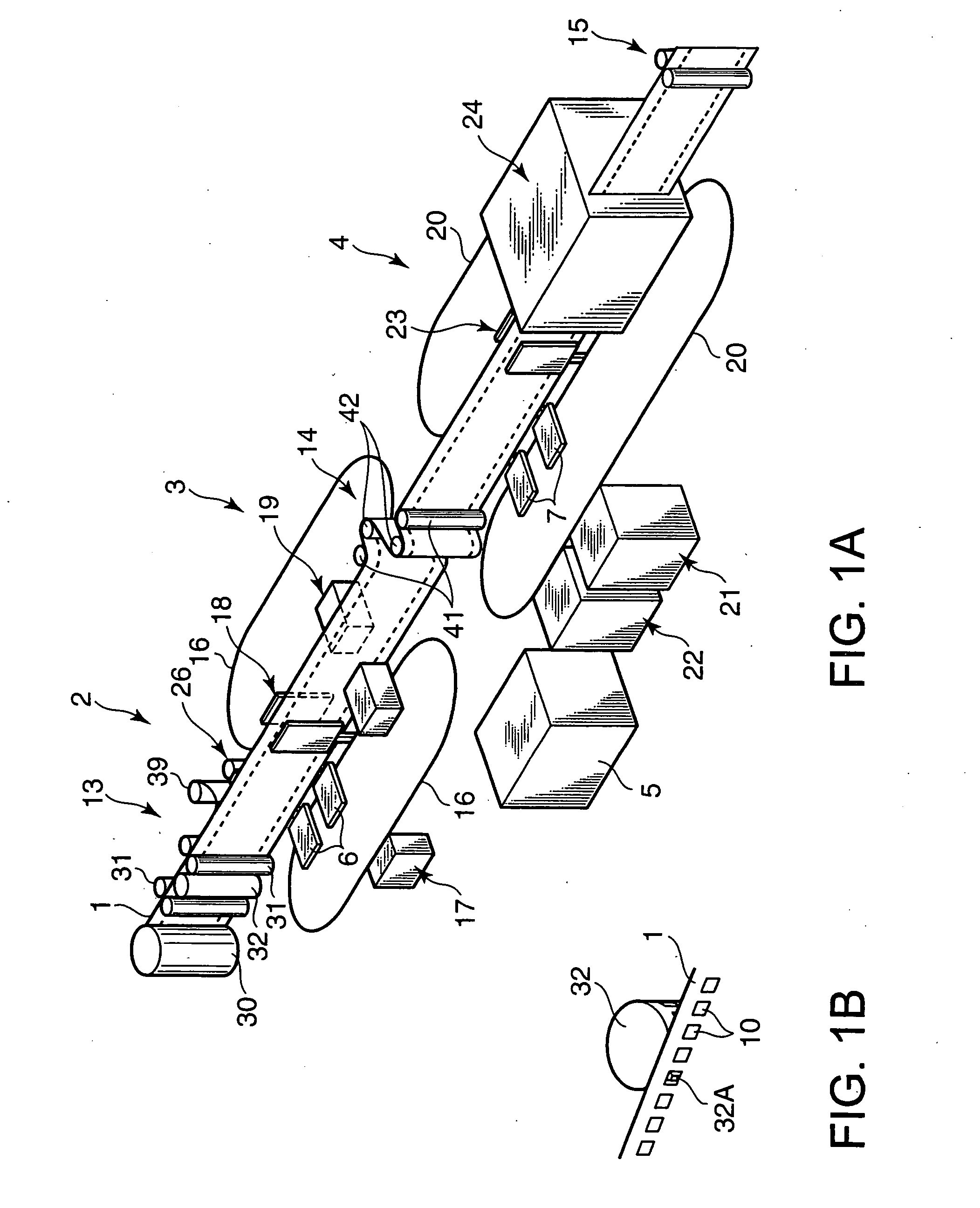
[0098] The fuel cell manufacturing device comprises an MEA conveyance unit 200 and a pair of separator conveyance units 40 disposed on either side thereof.

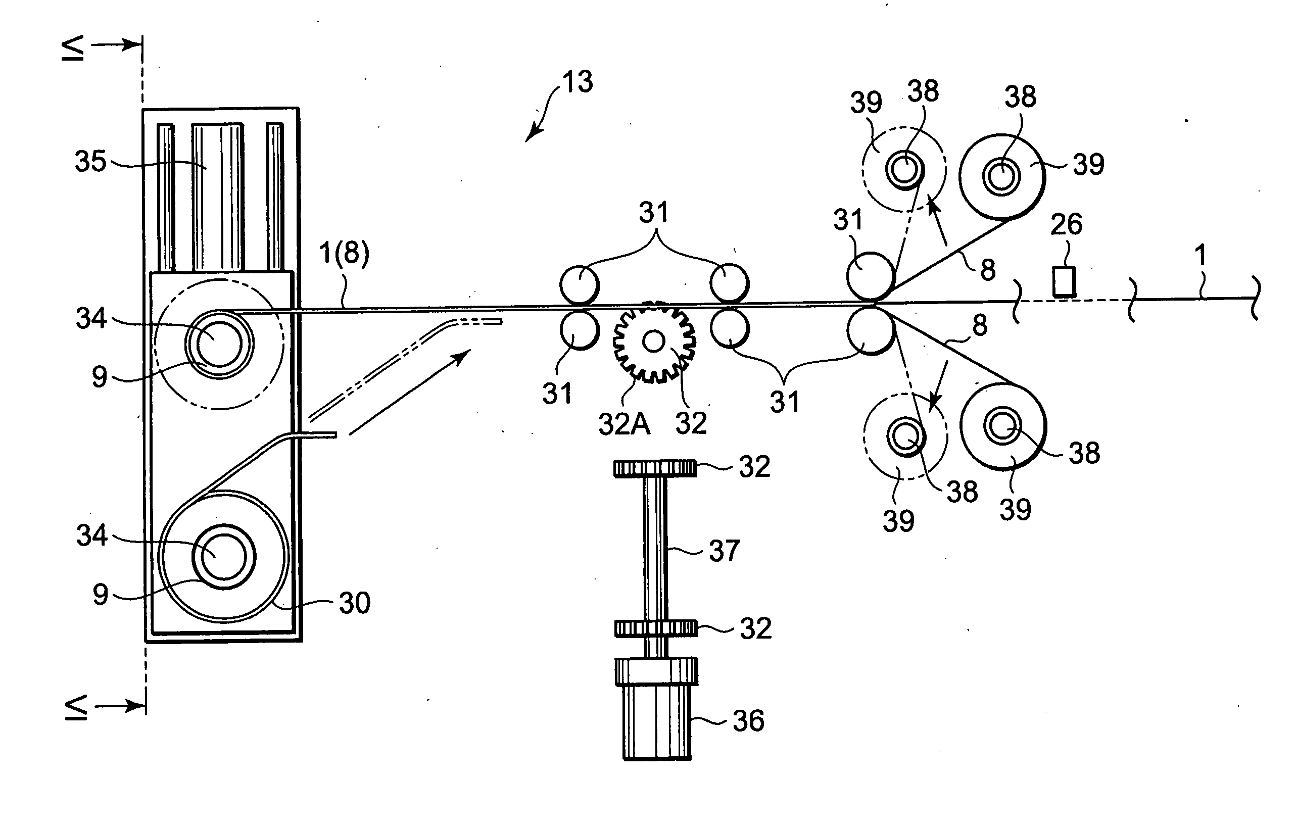
[0099] In the MEA conveyance unit 200, the MEA 1 is fed from the roll 30 of the MEA 1, which is wound around the reel 9, by a conveyance roller 32. Similarly to the first embodiment, catalyst layers are formed on the MEA 1 at fixed intervals and the conveyance holes 10 are formed at fixed intervals on the two outer sides of the catalyst layer. In contrast to the first embodiment, however, a protective sheet is not adhered to the MEA 1 as it passes the conveyance roller 132. Projections which engage with the holes 10 are formed on the outer periphery of the conveyance roller 132.

[01...

first embodiment

[0101] The separator conveyance unit 40 comprises a conveyance roller 132A which comprises similar projections to those formed on the conveyance roller 132 and rotates in synchronization with the conveyance roller 132. The conveyance roller 132A conveys the film 95 by rotating while the projections 132B engage with the holes 10A. The sealing agent application nozzle 78 is provided upstream of the conveyance roller 132A in the movement direction of the film 95. Similarly to the first embodiment, the sealing agent application nozzle 78 applies the sealing agent to a predetermined position, including the outer peripheral portion, of the separator 7.

[0102] Thus the film 95 adhered with the separators 7 is supplied to the two sides of the MEA 1. The separators 7 on the film 95 are pressed onto the MEA 1 by a pair of joining rollers 133.

[0103] As shown in FIG. 16C, projections 320 which penetrate the conveyance holes 10 and the holes 10A are formed on the outer periphery of one of the pa...

third embodiment

[0105] Next, referring to FIGS. 17A-28, this invention will be described.

[0106] First, referring to FIG. 17A, a fuel cell stack manufacturing device comprises a lamination unit 201, and an MEA conveyance unit 202 which supplies the lamination unit 201 with the MEA 1. The fuel cell manufacturing device further comprises a laminate supply unit 203 shown in FIG. 21, which supplies the lamination unit 201 with a laminate 210.

[0107] In the MEA conveyance unit 202, the MEA 1 is fed from the roll 30 of the MEA 1, which is wound around the reel 9, by two pairs of conveyance rollers 211 and supplied to the lamination unit 201.

[0108] Referring to FIG. 18, catalyst layers are formed on both surfaces of the MEA 1 in advance, and conveyance holes 212 are formed on both side portions of the MEA 1 at equal intervals in the lengthwise direction of the MEA 1. Furthermore, to assist the lamination unit 201 in cutting out the MEA 1, a rectangular perforation 213 is formed on the outer periphery of t...


PUM


Abstract

A fuel cell is manufactured using a polymer electrolyte membrane (1). A catalyst layer (12) is formed at fixed intervals on the surface of the strip-form polymer electrolyte membrane (1) in the lengthwise direction thereof, and conveyance holes (10) are formed in series at fixed intervals on the two side portions thereof. By rotating a conveyance roller (32) comprising on its outer periphery projections which engage with the holes (10), the polymer electrolyte membrane (1) is fed from a reel (9). A GDL (6) and a separator (7) are adhered to the fed polymer electrolyte membrane (1) at a predetermined processing timing based on the rotation speed of the conveyance roller (32), and thus the fuel cell is manufactured efficiently while the GDL (6) and separator (7) are laminated onto the catalyst layer (12) accurately.

Description

FIELD OF THE INVENTION [0001] This invention relates to the manufacture of a fuel cell. BACKGROUND OF THE INVENTION [0002] JP2001-236971A, published by the Japan Patent Office in 2001, discloses a method of obtaining a plurality of fuel cells in a continuous strip form by feeding one end of a polymer electrolyte membrane from a roll of polymer electrolyte membrane using a roller, and then performing catalyst layer formation, gas diffusion layer formation, and separator joining processes on the moving polymer electrolyte membrane in sequence. SUMMARY OF THE INVENTION [0003] When this manufacturing method is applied, the polymer electrolyte membrane must be fed in fixed lengths and stopped precisely in the locations at which each process is performed. However, taking roller slippage into consideration, such positioning is not easy. [0004] It is therefore an object of this invention to increase the feeding precision with which a polymer electrolyte membrane is fed from a roll so that t...

Claims


Application Information

Patent Timeline
IPC IPC(8): H01M8/10B05D5/12H01M4/88H01M8/24H01M8/00H01M8/02
CPCB32B37/223B32B38/1841B32B2457/18H01M4/881H01M8/1002H01M2008/1095Y02E60/521H01M8/1007H01M8/2404Y02P70/50Y02E60/50H01M8/24H01M8/00
Inventor KURAMOCHI, TAKEHARUIWAMOTO, MASANORIKATSU, MASAHIKOEGUCHI, KAORUOMATA, MASAHIROKANAFUSA, HIDETOMUTO, YOSHIKI
Owner NISSAN MOTOR CO LTD
Why Eureka
Try Eureka