
Wireless communication system, weight control apparatus, and weight vector generation method

a communication system and control apparatus technology, applied in telephonic communication, electrical equipment, substation equipment, etc., can solve the problems of large apparatus scale and difficulty in forming a situation in which only terminals or base stations can transmit packets

Inactive Publication Date: 2007-05-24
KASAMI HIDEO +1
View PDF10 Cites 31 Cited by
  • Summary
  • Abstract
  • Description
  • Claims
  • Application Information

AI Technical Summary

Benefits of technology

"The present invention provides a wireless communication system, weight control apparatus, and weight vector generation method that can prevent the number of weights to be held from increasing abruptly even when the number of terminals increases, by not preparing orthogonal beams in correspondence with combinations of terminals upon space-division multiplex access. Additionally, the invention reduces the apparatus scale by limiting the number of interference waves to be suppressed in a wireless communication system that makes packet communications using CSMA / CA, and forms beams that remove these interference waves. The invention also allows simultaneous communications with a plurality of terminals by space-division multiplex access, by using a plurality of antenna elements, beam forming units, and a controller to set weight vectors used to control weighting and combining in the beam forming units. The controller calculates and stores at least one of the weight vectors used to form a beam having null directionality toward the unregistered terminal and maximum directionality toward a specific area other than an area where the unregistered terminal is located of areas obtained by dividing a cover area covered by the wireless communication system."

Problems solved by technology

However, in order to suppress all co-channel interference waves from a neighboring cell, the number of antenna elements must be increased, resulting in a large apparatus scale.
Since the IEEE802.11 wireless LAN system using CSMA / CA does not make integrated control of packet transmission, as described above, it is difficult to form a situation in which only terminals or base stations to be suppressed transmit packets.

Method used


Image

  • Wireless communication system, weight control apparatus, and weight vector generation method
  • Wireless communication system, weight control apparatus, and weight vector generation method
  • Wireless communication system, weight control apparatus, and weight vector generation method

Examples


first embodiment

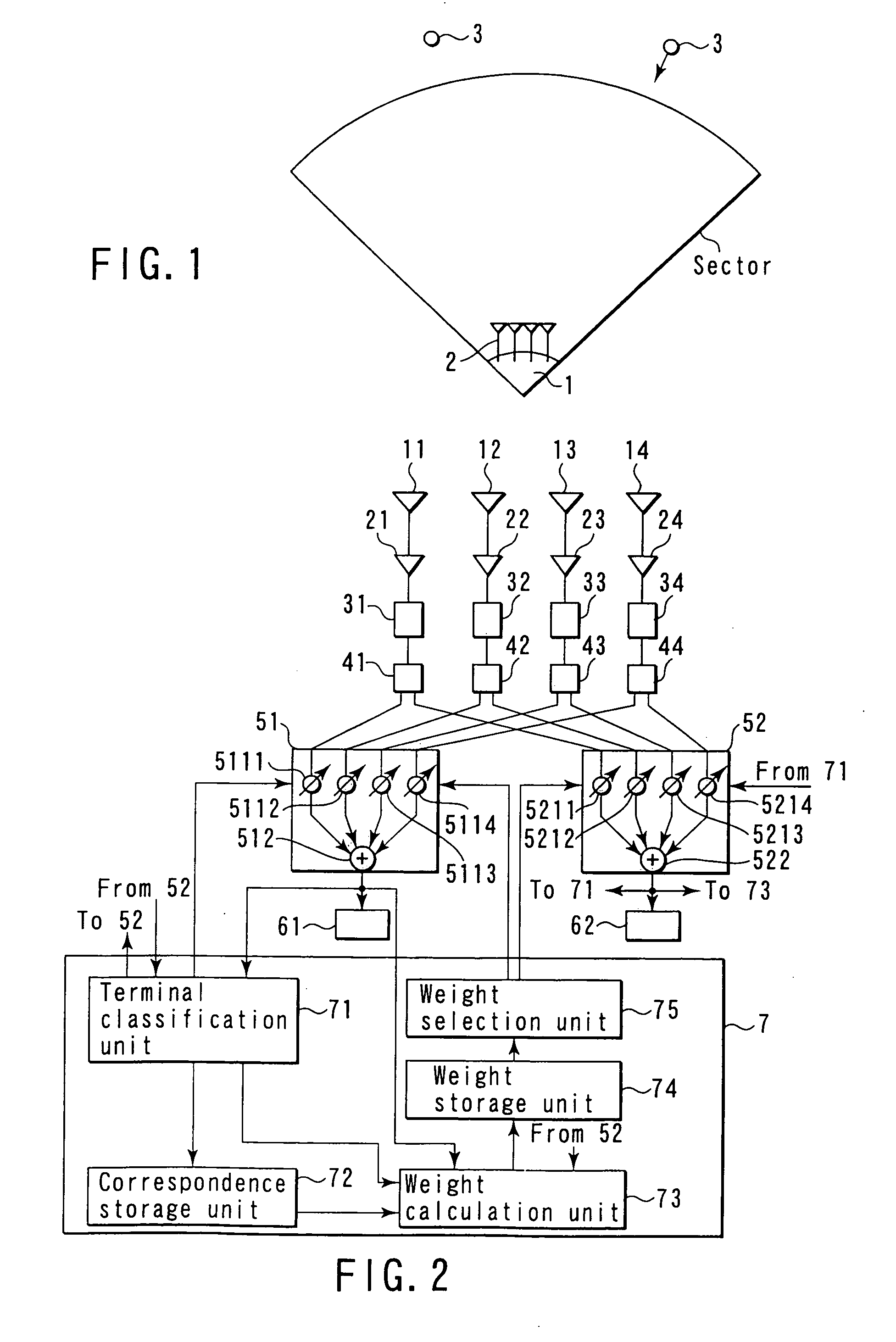
[0042]FIG. 1 shows an example of an FWA (Fixed Wireless Access) system including a base station 1 to which the first embodiment of the present invention is applied.

[0043] A base station 1 comprises an adaptive array (wireless communication system) 2, and can make simultaneous communications with a plurality of terminals 3 via a single channel by avoiding interference between terminals using the adaptive array 2. Note that FIG. 1 illustrates a 90° sector, but the present invention is not limited to this.

[0044] Note that this embodiment will exemplify space-division multiplex access (SDMA) of two terminals using an adaptive array consisting of four antenna elements.

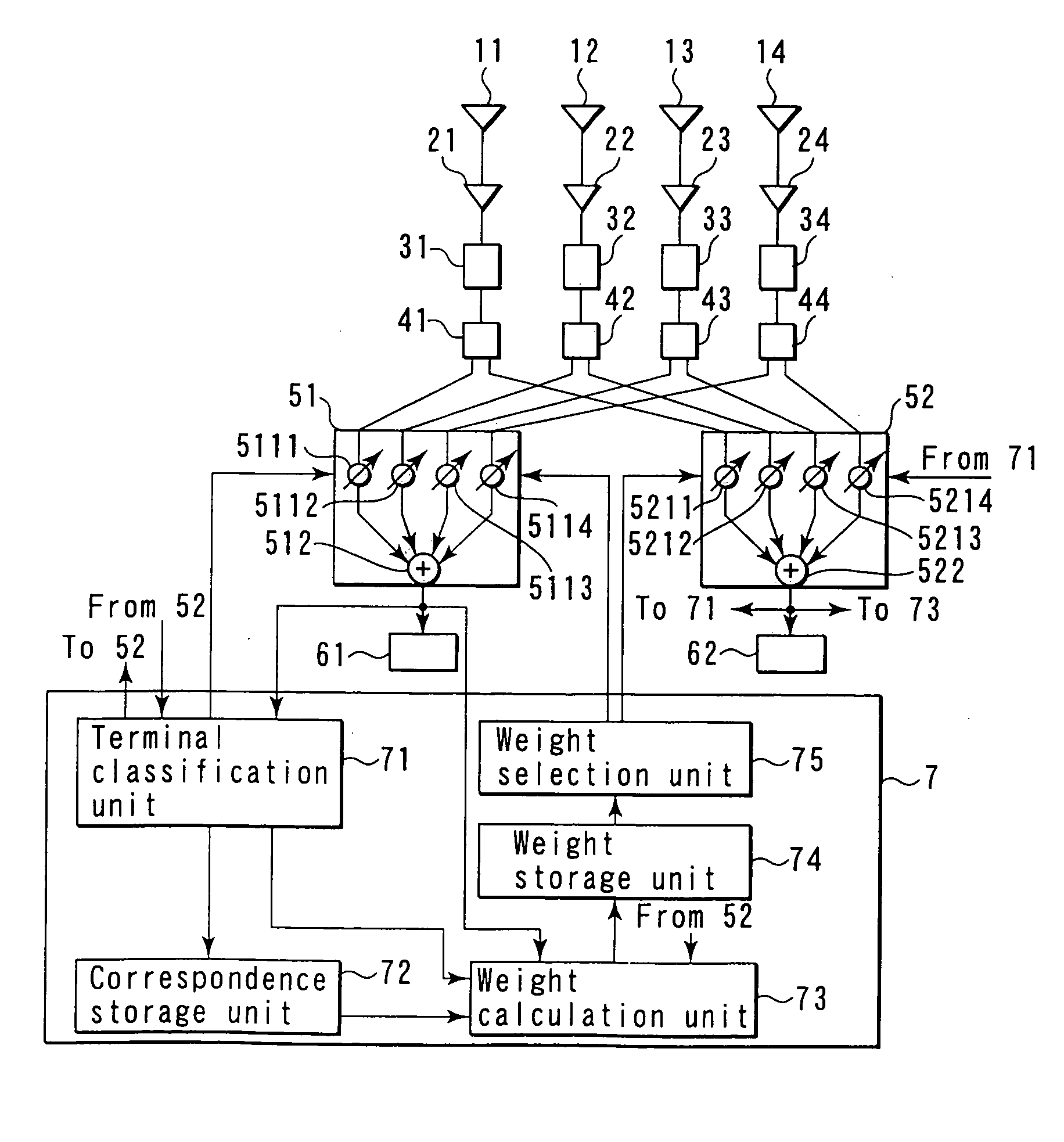
[0045]FIG. 2 shows an example of the arrangement of the adaptive array arranged in the base station according to this embodiment.

[0046] As shown in FIG. 2, the adaptive array of this embodiment comprises m (m is a plural number; m=4 in FIG. 2) antenna elements 11 to 14, m amplifiers (low noise amplifiers) 21 to 24, m fr...

second embodiment

[0103] Since this embodiment is basically the same as the first embodiment, differences between this embodiment and the first embodiment will be mainly explained below.

[0104]FIG. 13 shows an example of the arrangement of an adaptive array arranged in a base station according to this embodiment.

[0105] As shown in the example of the arrangement of the adaptive array in FIG. 13, this embodiment is different from the first embodiment in that an initial value selection unit 76 is added to the example of the arrangement of the adaptive array of the first embodiment shown in FIG. 2.

[0106] This initial value selection unit 76 selects the weight stored in the initial weight storage device 711 of the terminal classification unit 71 or that (used to form a beam having null directionality toward a given terminal and maximum directionality toward the range of a given area) stored in the weight storage unit 74 on the basis of the registration record (terminal-area correspondence information) s...

third embodiment

[0136] In the third embodiment, the present invention is applied to an IEEE802.11 wireless LAN system using CSMA / CA. Since the conventional IEEE802.11 wireless LAN system using CSMA / CA does not make integrated control of packet transmission, as described above, it is difficult to obtain a situation in which only a terminal to be suppressed or base station transmits packets. As a result, a terminal of the self cell transmits packets in place of the terminal or base station to be suppressed, and unwanted beams that suppress such packets are formed. This embodiment solves this problem.

[0137]FIG. 18 shows an example of a wireless communication system according to the third embodiment of the present invention.

[0138] Base stations (AP) 111 to 114, 211 to 214, and 311 to 314 respectively comprise transmission adaptive arrays (transmission SA) 131 to 134, 231 to 234, and 331 to 334 and reception adaptive arrays (reception SA) 141 to 144, 241 to 244, and 341 to 344, which share array anten...


PUM


Abstract

Signals received by a plurality of antenna elements are supplied to a beam forming circuit via a distributor. The beam forming circuit weights and combines the signals to output a reception signal corresponding to a beam having a predetermined directionality pattern. A weight used to control weighting and combining is set by a weight controller. Upon receiving a registration request from an unregistered terminal, the weight controller calculates a weight vector used to form a beam having null directionality toward that terminal, and maximum directionality toward the range of an area other than an area where the terminal is located of a plurality of areas obtained by dividing the area covered by the antenna elements in accordance with direction.

Description

CROSS-REFERENCE TO RELATED APPLICATIONS [0001] This application is based upon and claims the benefit of priority from the prior Japanese Patent Application No. 2000-333202, filed Oct. 31, 2000, the entire contents of which are incorporated herein by reference. BACKGROUND OF THE INVENTION [0002] 1. Field of the Invention [0003] The present invention relates to a wireless communication system for making space-division multiple access, a weight control apparatus, and a weight vector generation method. [0004] 2. Description of the Related Art [0005] In an FWA (Fixed Wireless Access) system, a base station and fixed terminal station make wireless, high-speed communications. In a point-to-multipoint (P-MP) system, a base station communicates with a plurality of terminal stations. In the P-MP system, space-division multiplex access (SDMA) is known as means for increasing the subscriber capacity. As shown in FIG. 16, an adaptive array 1002 arranged in a base station 1001 forms orthogonal be...

Claims


Application Information

Patent Timeline
Patent Type & Authority Applications(United States)
IPC IPC(8): H04B1/00H04W16/24H04W16/28
CPCH04W16/24H04W16/28
Inventor KASAMI, HIDEOOBAYASHI, SHUICHI
Owner KASAMI HIDEO
Learn More