Automated stimulus artifact removal for nerve conduction studies

Active Publication Date: 2007-05-24
NEUROMETRIX
View PDF8 Cites 28 Cited by
  • Summary
  • Abstract
  • Description
  • Claims
  • Application Information

AI Technical Summary

Benefits of technology

[0016] The present invention provides a novel method and apparatus for stimulus artifact removal for automated NCS testing which can be done by personnel without specialized training. While the discussion below often refers to sensory (SNAP) signals, the present invention is applicable to both sensory (SNAP) and motor (CMAP) recordings. The present invention may also be applied to other electrophysiological recordings where stimulus artifact is present. The novel method and apparatus are robust enough to handle the most problematic cases of SA contamination, i.e., those in which the SA and the signal of interest are overlapped in time as well as in frequency. The novel method and apparatus are also robust enough to operate on potentially noisy data (from either sensory or motor NCS tests) that are collected using minimal waveform averaging, and do not pose additional hardware requirements such as the use of a reference channel.
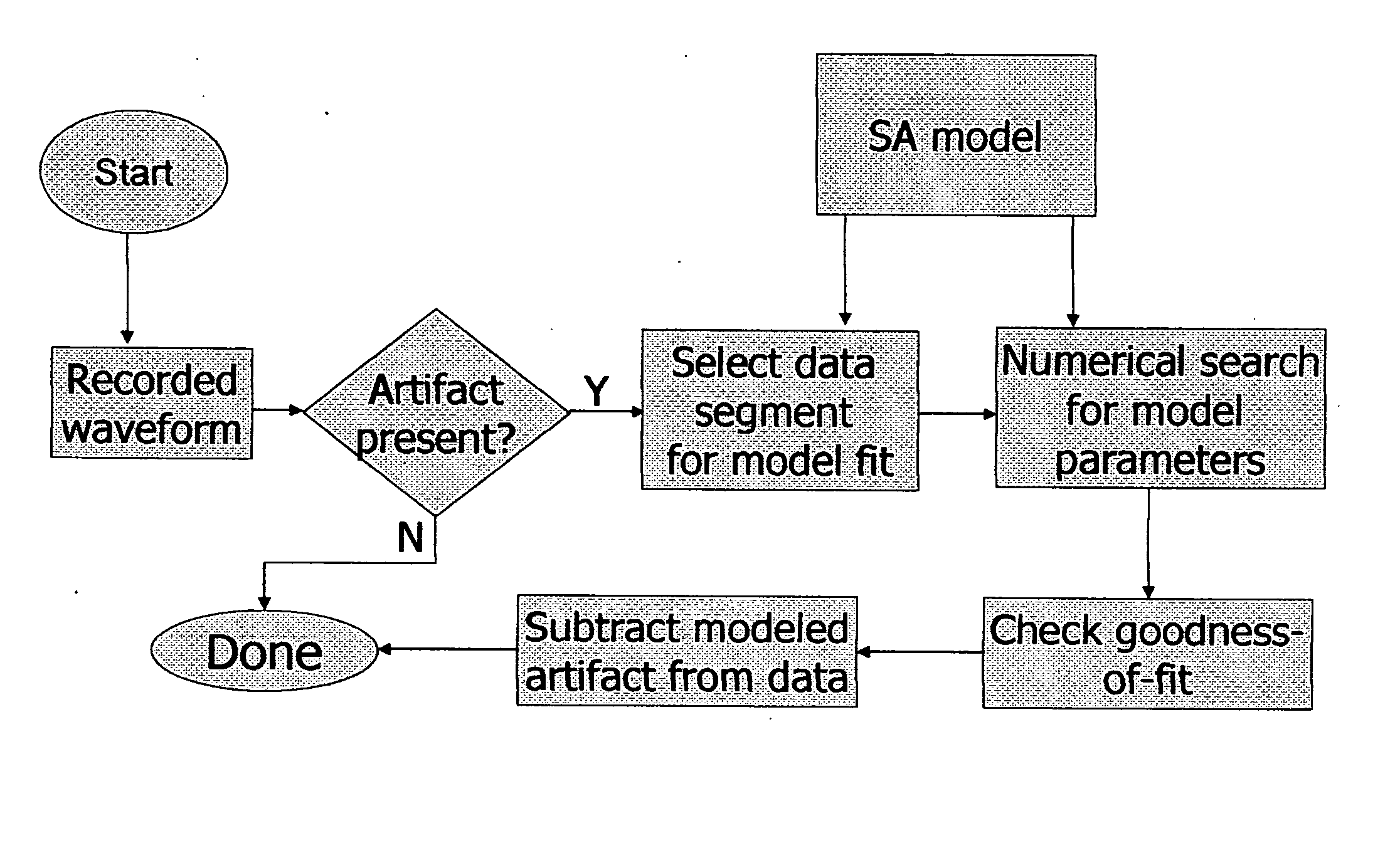
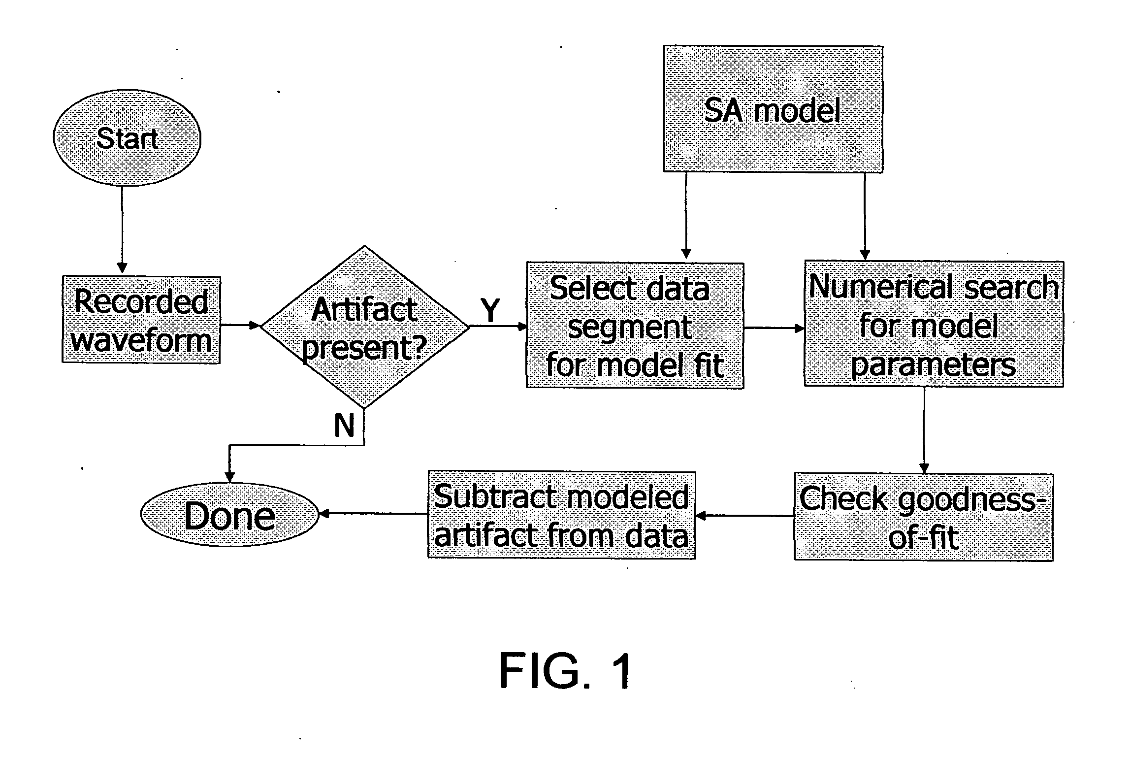
[0030] (4) Next, a procedure is provided for estimating SA model parameters from the data values in the fit region. This procedure can use any of several numerical techniques for parameter estimation (e.g., optimized numerical solvers, brute-force solvers, look-up table approximations, etc.). This procedure may be extended to enforce additional constraints on the solution outside the SA fit region. For example, in one embodiment, the estimated SA waveform is required to meet specified constraints late in time as well as providing the best possible fit in the SA fit region. This particular embodiment can be useful to avoid “over-fitting” the model to the data from the identified SA fit region.
[0033] (7) Finally, the invention also provides a procedure for combining information across multiple waveforms. In one embodiment, in addition to seeking good correspondence between the SA model and the data, good correspondence is also sought between the SA model and other waveforms acquired with similar stimulus parameters. This procedure seeks to minimize the possibility that insufficiently-corrected data will be accepted for clinical analysis. Other embodiments of this procedure are outlined below.

Problems solved by technology

The stimulus can cause unwanted artifacts that can complicate the interpretation of recorded signals.
Unreliable parameter estimates' reduce NCS accuracy and may even lead to incorrect diagnoses.
A common problem in NCS is that a stimulus artifact (SA) can distort the nerve signal.
Thus, it is not always possible to separate the stimulator and detector electrodes by a distance sufficient to ensure that the signal of interest arrives after the stimulus artifact has decayed away.
The primary disadvantage of this approach is that it requires a highly skilled specialist to perform the NCS test.
This is contrary to the goal of automated NCS testing, which seeks to use automated NCS test devices which require minimal user training and interaction.
However, this approach is not practical for NCS applications, since the anatomical differences between patients mean that a single electrode geometry will not be optimal for all patients.
However, this approach generally requires more complicated sensors and data acquisition systems, and would increase the cost of an NCS study.
Unfortunately, the usefulness of adaptive approaches may be limited, because a good reference channel may not be available (i.e., the reference channel may be contaminated by the signal of interest, or the SA in the reference channel may have a different morphology than that in the primary channel, or both).
In addition, recording a reference channel increases hardware requirements and drives up the cost and complexity of NCS equipment.
While this type of approach has merit, it can be difficult to find simple shapes that can account for the SA morphology throughout the full NCS waveform.
However, such piecewise curve fitting generally complicates the curve fitting procedure and can actually make it more prone to error.
However, as is known to those skilled in the art, waveform reconstruction using deconvolution is subject to errors when the input data is noisy.
However, in the NCS application, such waveform averaging would require patients to receive additional electrical shocks, making NCS studies longer and less comfortable for the patients.

Method used


Image

  • Automated stimulus artifact removal for nerve conduction studies
  • Automated stimulus artifact removal for nerve conduction studies
  • Automated stimulus artifact removal for nerve conduction studies

Examples


first embodiment

[0170] In this procedure, a requirement may be imposed that SA removal be successful on a number of successive waveforms with similar stimulus parameters. If the algorithm judges that a good fit is achieved on multiple traces, the probability is higher that the SA model accurately describes the data.

second embodiment

[0171] In a second embodiment, SA parameter estimates obtained using one waveform may be used when estimating SA parameters for a second waveform. For example, an assumption may be made that the time constant for a decaying exponential will be nearly identical on subsequent waveforms. This may be used to constrain the estimation process.

[0172] Note that for some electrode locations, there may be more or less variation in the SA seen in waveforms with similar stimulation parameters. In situations where SA varies noticeably between stimuli, SA removal may be applied before any waveform averaging is carried out. After SA is removed from multiple waveforms, the corrected waveforms are averaged to create data for further analysis.


PUM


Abstract

A method for the automated removal of a stimulus artifact from an electrophysiological signal waveform, wherein the novel method comprises: providing a model of the stimulus artifact that is physically derived and is based on known properties of the electrophysiological signal waveform acquisition hardware and stimulator; and filtering the stimulus artifact out of the electrophysiological signal waveform using the model.

Description

REFERENCE TO PENDING PRIOR PATENT APPLICATION [0001] This patent application claims benefit of pending prior U.S. Provisional Patent Application Ser. No. 60 / 728,460, filed Oct. 20, 2005 by Brian H. Tracey et al. for AUTOMATED STIMULUS ARTIFACT REMOVAL FOR NERVE CONDUCTION STUDIES (Attorney's Docket No. NEURO-14 PROV), which patent application is hereby incorporated herein by reference.FIELD OF THE INVENTION [0002] This invention relates to apparatus and methods for the assessment of electrophysiological signals. More particularly, this invention relates to improving the accuracy of such electrophysiological assessment by automatically removing signal artifacts created by electrical stimulation. While the invention is generally applicable to a wide range of electrophysiological signals, it is focused on artifact removal for nerve conduction studies. BACKGROUND OF THE INVENTION [0003] In a variety of biomedical applications, an electrical stimulus is applied to tissue in order to evok...

Claims


Application Information

Patent Timeline
IPC IPC(8): A61B5/04A61B5/05
CPCA61B5/72A61B5/04001A61B5/7217A61B5/7203A61B5/7207A61B5/4041A61B5/24
Inventor TRACEY, BRIANKRISHNAMACHARI, SRIVATHSANGOZANI, SHAI N.
Owner NEUROMETRIX
Why Eureka
Try Eureka