Modular patella instrument

a module and instrument technology, applied in the field of modules, can solve the problem of not providing any method of setting the depth of the patella milling, and achieve the effect of facilitating the preparation of the natural patella

Active Publication Date: 2007-05-24
HOWMEDICA OSTEONICS CORP
View PDF29 Cites 165 Cited by
  • Summary
  • Abstract
  • Description
  • Claims
  • Application Information

AI Technical Summary

Benefits of technology

[0012] It is an object of the invention to provide an improved apparatus and method for facilitating the preparation of the natural patella to receive a patellar prosthesis.
[0013] It is an additional object of the invention to provide a clamping system which can hold the patella in position during resection and which can be set to either resect a predetermined amount of bone from the patella or, alternately, to set the depth of the remaining bone on the patella.
[0014] It is an additional object of the invention to provide a clamping system wherein various modular instruments may be easily attached and removed from the gripping portion of the clamping system.
[0017] The shaft includes at one end a cutting element such as a reamer or end mill which is used to shape the posterior surface of the patella. At the other end the shaft includes a coupling portion for engaging a rotary tool such as a drill chuck mounted on an electric battery or air powered tool. The shaft has a collar engaging portion with external ratchet like teeth which selectively engage complementary internal teeth on the collar. The teeth on the collar may be moveable into and out of engagement with the teeth on the shaft so that the collar may be easily adjusted axially along the shaft.

Problems solved by technology

Corvelli et al. does not provide any method of setting the depth of the patella milling based on the amount of bone remaining.

Method used


Image

  • Modular patella instrument
  • Modular patella instrument
  • Modular patella instrument

Examples


Embodiment Construction

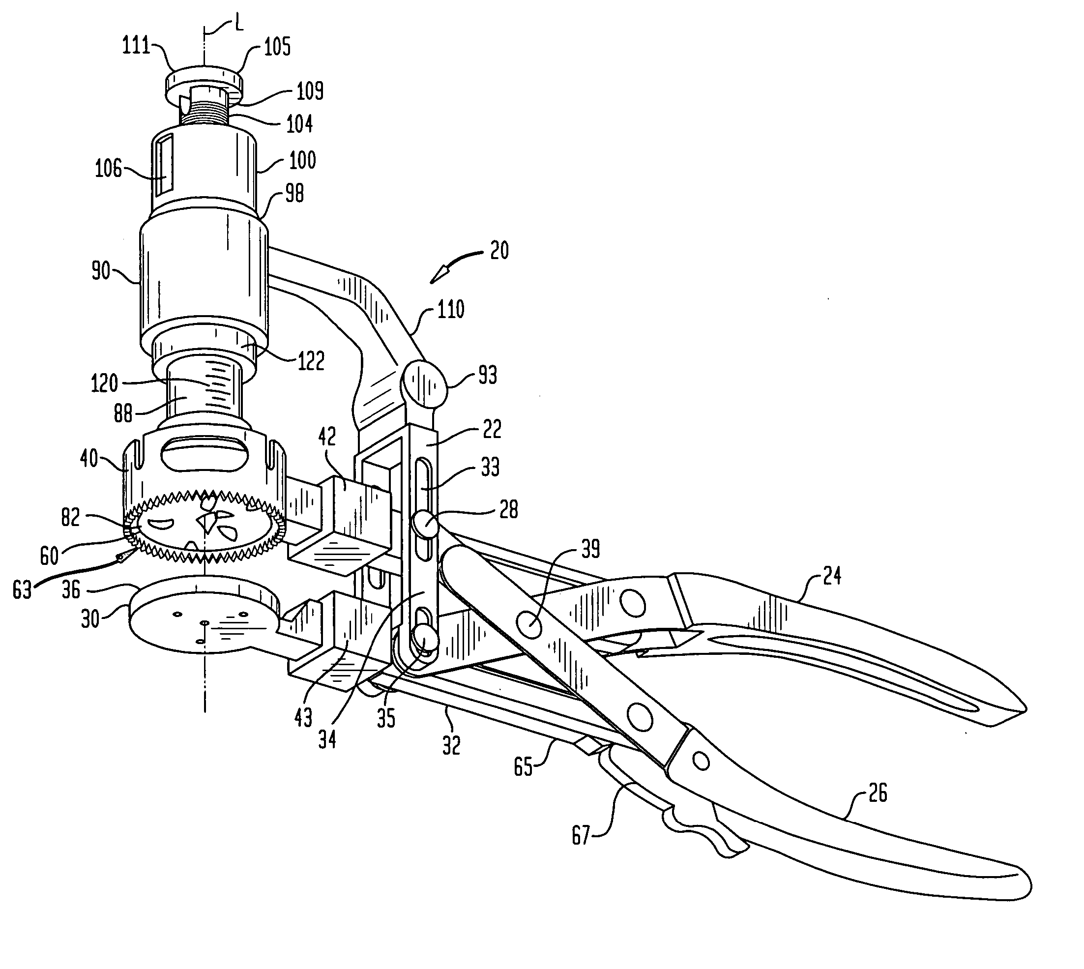
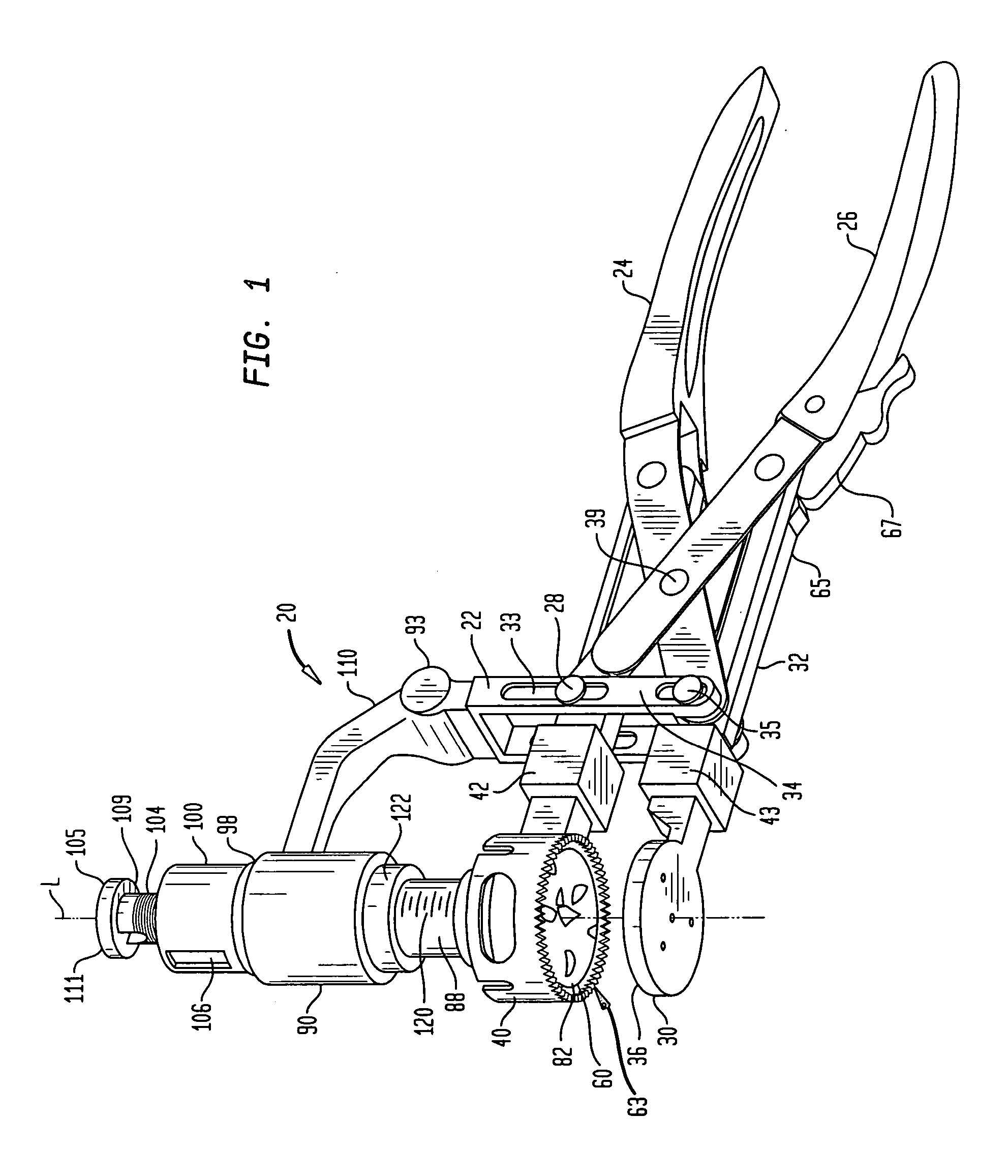
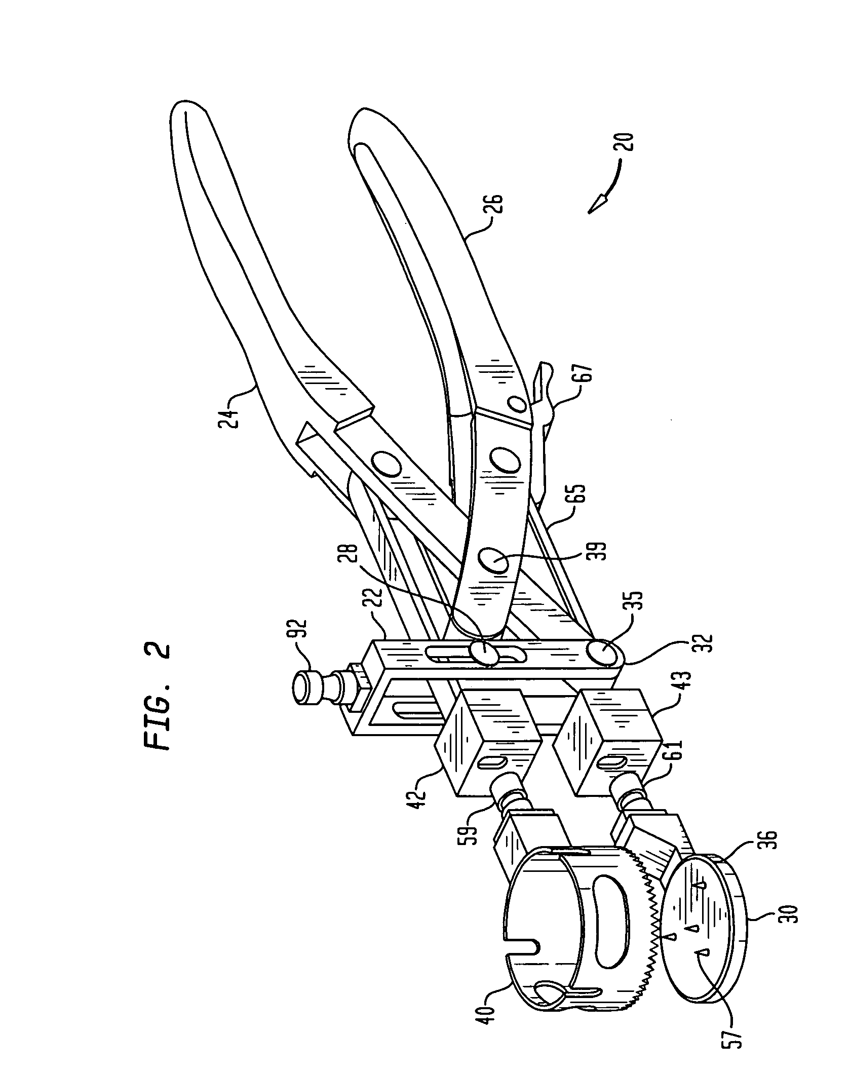
[0033] Referring now to the drawings, and especially to FIG. 1 thereof, an apparatus constructed in accordance with the present invention is shown in the form of a patella clamp 20 having a frame 22. An upper arm handle 24 is affixed to the frame 22 and a lower arm handle 26 is mounted upon the frame 22 at pin 28 for sliding movement in a slot 33 of frame 22 toward and away from the upper handle 24. A support platform 30 is attached to frame 22 at a lower end 32 of a side bar 34 of the frame 22. Preferably, platform 30 is removably attached to a carrier 43 which in turn is fixed to side bar 34. A pin 35 mounts arm 24 to frame 22. Platform 30 includes a bone contacting reference surface 36 extending laterally across the upper surface of platform 30. Side bar 34 also include slot 33 in which pin 28 slides. In the preferred embodiment, a patella clamping member shown in the form of a barrel or tubular shaped clamp member 40. Clamp 40 is attached to lower arm 26 by a modular carrier 42 ...


PUM


Abstract

A patella clamp has a first part including a reference surface engageable with the anterior surface of a patella. The first part includes a stop surface spaced from the reference surface. A second clamping part is provided which is moveable with respect to the first clamping part. A cutting element coupled to the first clamping part is moveable with respect to the first part. The cutting element includes a shaft with an adjustable collar mounted on the shaft for movement with respect to the longitudinal axis of the shaft and cutting element. The adjustable collar on the shaft is engageable with a stop surface on the first part for spacing the cutting element a desired distance from the reference surface. A pair of gages are provided for selectively setting the position of the adjustable collar with respect to either the amount of patella bone being removed or the amount of patella bone remaining.

Description

[0001] This application is a divisional of U.S. application Ser. No. 10 / 366,014, filed on Feb. 13, 2003, the disclosure of which is incorporated herein by reference.BACKGROUND OF THE INVENTION [0002] A patellar clamp and reamer are used during a total knee arthroplasty procedure to prepare the posterior surface of a patellar bone to accept a prosthetic implant. [0003] Typically, a surgeon will select to install a patellar prosthesis either by utilizing a resurfacing technique wherein the prosthetic patella will be positioned on the prepared surface of the patella or by an insetting technique wherein the prosthetic patella will be recessed or inset into the prepared surface of the patella. Accordingly, two varieties of guides could be available for connection to the patellar clamp and could be interchangeably connectable to the clamp. The interchangeable guides permit a surgeon to use the patellar clamp during either a total patellar bone resurfacing procedure or a patella insetting ...

Claims


Application Information

Patent Timeline
Patent Type & Authority Applications(United States)
IPC IPC(8): A61B17/17A61B17/90A61B17/16A61B19/00
CPCA61B17/1677A61B2019/304A61B2090/034
Inventor MARCHYN, DUANE J.STARACE, LOUIS M.NEAL, DAVID J.BARILE, GENNARO
Owner HOWMEDICA OSTEONICS CORP
Why Eureka
Try Eureka