
System to monitor the health of a structure, sensor nodes, program product, and related methods

a sensor system and structure technology, applied in the field of multi-node sensor systems, can solve the problems of increasing the weight and complexity of the component being monitored and/or the associated structure or component, extensive repair costs and down time, and affecting the health of the structur

Active Publication Date: 2007-05-24
LOCKHEED MARTIN CORP
View PDF14 Cites 75 Cited by
  • Summary
  • Abstract
  • Description
  • Claims
  • Application Information

AI Technical Summary

Benefits of technology

The present invention provides a communication system that can manage data collisions between sensor nodes and allow for useful communication. The system includes a plurality of health monitoring sensor nodes connected to a structure, each with a processor and an antenna arrangement. The system also includes an interrogator with a preselected transmission power and interrogation signal frequency spectrum, and a preselected data signal receive frequency spectrum that matches the resonant frequency of the sensor nodes. The system can selectively tune the antenna arrangement to the interrogator and detune from other sensor nodes to minimize data collisions. The processor can signal a switch to vary the load seen by the interrogator or the reflection cross-section of the antenna arrangement. The technical effects of the invention include reducing data collisions, minimizing complexity, and improving efficiency of multiple access communication.

Problems solved by technology

Various types of platforms such as, for example, aircraft structural components, aircraft skins, or other related components, when in operation are subjected to various environmental conditions such as stress and strain, exposure to temperature extremes, and / or significant vibration energy.
Due to the various environmental conditions such components can suffer material degradation over time.
Such wiring can undesirably result in increased weight and complexity of the component being monitored and / or of the associated structure or component and are subject to damage or breakage requiring extensive repair costs and down time.
Depending upon available space, batteries can be inappropriate due to their size.
Batteries can also have a limited service life and therefore typically require periodic inspection and / or replacement, are often positioned in locations difficult to reach, and often require costly disassembly and reassembly of the sensor or component to perform service on the battery.
Further, batteries may not be suitable due to environmental constraints, i.e., temperature changes often affect battery performance.
Such fiber-optic conductors, as with electrical conductors, can significantly raise the complexity of the component and / or deployment of the sensor system.
This type of sensor can typically consume very low amounts of power in the microwatt range.
The passive sensors, however, do not actively transmit such data, but instead receive energy from, for example, a mobile vehicle or handheld base device or reader positioned adjacent each wireless sensor, which provides power to extract the sensor data.
In structural health monitoring applications or other applications in which a large number of wireless sensors may be in close proximity to each other, many of the passive communication schemes, due to limitations on available power, rely on inductive coupling and backscatter coupling, such as that described above, and thus, do not have the ability to be switched off.
If a large number of passive sensors are in close proximity to each other, collisions in the physical layer are likely to occur, thus making data communication very inefficient.
Some of these techniques do not have an equivalent in passive communication schemes.
Others require processing and power to function, both of which add to the complexity of the communication system.

Method used


Image

  • System to monitor the health of a structure, sensor nodes, program product, and related methods
  • System to monitor the health of a structure, sensor nodes, program product, and related methods
  • System to monitor the health of a structure, sensor nodes, program product, and related methods

Examples


Embodiment Construction

[0033] The present invention will now be described more fully hereinafter with reference to the accompanying drawings, which illustrate embodiments of the invention. This invention may, however, be embodied in many different forms and should not be construed as limited to the illustrated embodiments set forth herein. Rather, these embodiments are provided so that this disclosure will be thorough and complete, and will fully convey the scope of the invention to those skilled in the art. Like numbers refer to like elements throughout. Prime notation, if used, indicates similar elements in alternative embodiments.

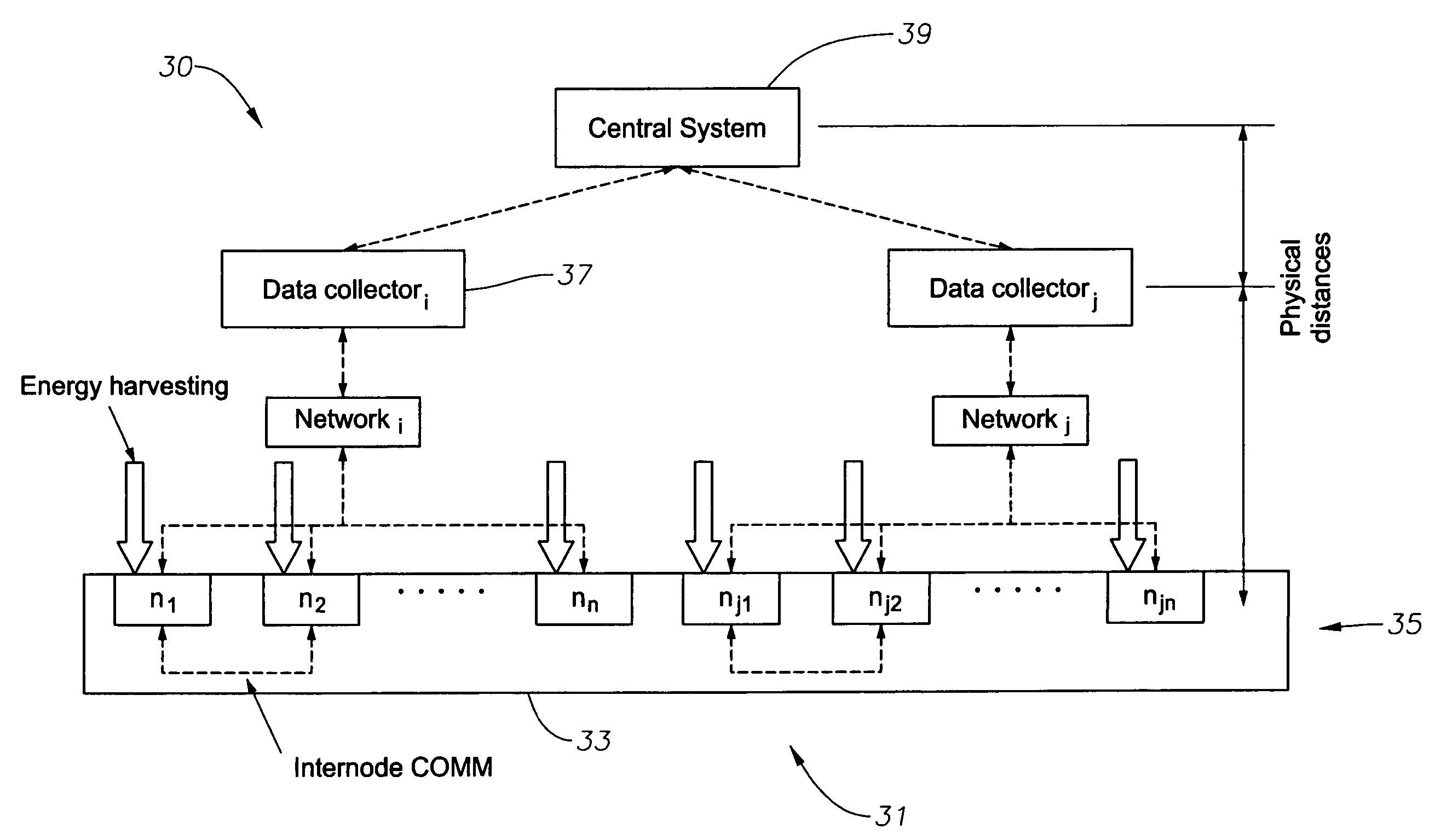
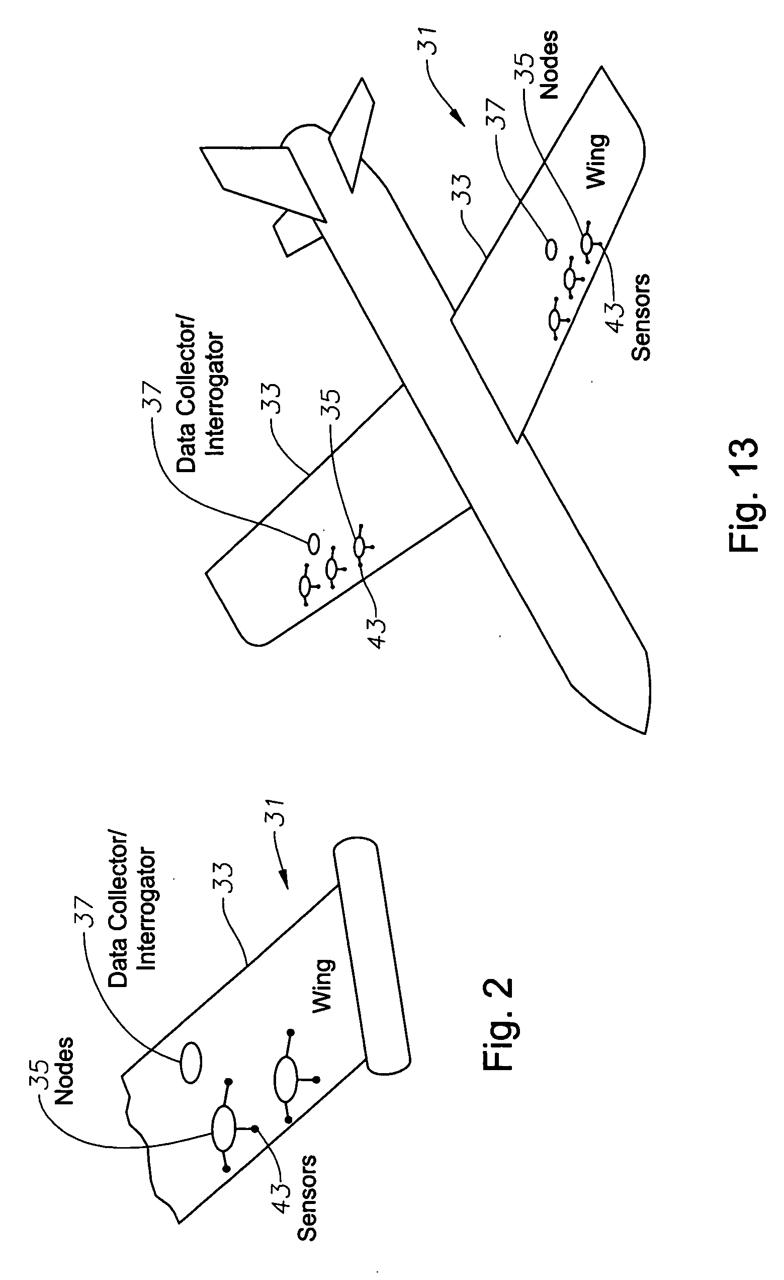
[0034] Low power structural health monitoring applications rely on the ability to efficiently communicate sensed data. In applications in which a large number of sensing nodes may be in close proximity to each other, communication between the sensor nodes and an interrogator or reader can be inefficient due to data collisions in the physical layer. Thus, advantageously, as il...


PUM


Abstract

A system to monitor the health of a structure, health monitoring sensor nodes, program product, and associated methods are provided. The system includes an array of health monitoring sensor nodes connected to or embedded within a structure to monitor the health of the structure. Each health monitoring sensor node includes sensor elements positioned to sense parameters of the structure and to provide data related to the parameters to a health monitoring sensor node interrogator. Each health monitoring sensor node has a tunable antenna arrangement individually tunable to minimize data collisions between each other of the health monitoring sensor nodes. Each health monitoring sensor node also includes a processor and memory in communication with the processor storing a parameter processing program product adapted to control tuning the antenna arrangement and providing data to the health monitoring sensor node interrogator.

Description

RELATED APPLICATIONS [0001] This invention is related to Non-Provisional application Ser. No. ______ by Berkcan, et al., titled “System to Monitor the Health of a Structure, Sensor Nodes, Program Product, and Related Methods,” filed on ______, 2005; and Non-Provisional application Ser. No. ______, by Andarawis, et al., titled “System to Monitor the Health of a Structure, Sensor Nodes, Program Product, and Related Methods,” filed on ______, 2005, all incorporated by reference herein in their entirety.BACKGROUND OF THE INVENTION [0002] 1. Field of The Invention [0003] The present invention relates generally to multi-node sensor systems. More specifically, the present invention relates to a system, sensor nodes, program product, and related methods to monitor the health of structural components and to minimize data collisions between nodes. [0004] 2. Description of the Related Art [0005] Various types of platforms such as, for example, aircraft structural components, aircraft skins, or...

Claims


Application Information

Patent Timeline
Patent Type & Authority Applications(United States)
IPC IPC(8): G06F11/00
CPCG01M5/00G01M5/0041G01M5/0066G01M5/0091G05B23/0213H04Q2209/10
Inventor ANDARAWIS, EMADBERKCAN, ERTUGRULDELGADO, ELADIORAO, SAMANTHA
Owner LOCKHEED MARTIN CORP
Learn More