Remote copy storage device system and a remote copy method

Inactive Publication Date: 2007-05-24
HITACHI LTD
View PDF6 Cites 19 Cited by
  • Summary
  • Abstract
  • Description
  • Claims
  • Application Information

AI Technical Summary

Benefits of technology

[0011] As described above, the center computer according to the invention monitors the loads of the communication lines connecting the center storage device and a plurality of remote storage devices and detects the communication line which is likely to undergo the overload. Then, the center computer instructs to switch the transmission route for the information of a part of the task processing among the information transmitted by using the transmission line to the center storage device and the plurality of remote storage devices. Receiving the information, the center storage device and the remote storage device switch the communication line to the one not using the c

Problems solved by technology

However, the technology disclosed in US2003/0051111 A1 does not consider an over-load of a communication load in a communication line for transmitting data from a copy origin to copy destinations when remote copy is made among three or more storage devices.
It has been found that when the communication load in the communication line becomes excessive, the copy processing gets delayed and owing to this delay, the task (business) processing performance of the computer drops.
Therefore, when the copy destinations of the remote copy are plural, the danger that the data quantity transmitted from the copy origin exceeds the transmission capacity of the copy origin or the transfer band of the communication line connecting the copy origin to the copy destinations is great, that is, the dang

Method used


Image

  • Remote copy storage device system and a remote copy method
  • Remote copy storage device system and a remote copy method
  • Remote copy storage device system and a remote copy method

Examples


Embodiment Construction

[0025] An embodiment of the invention will be hereinafter explained in detail with reference to the accompanying drawings, whenever necessary.

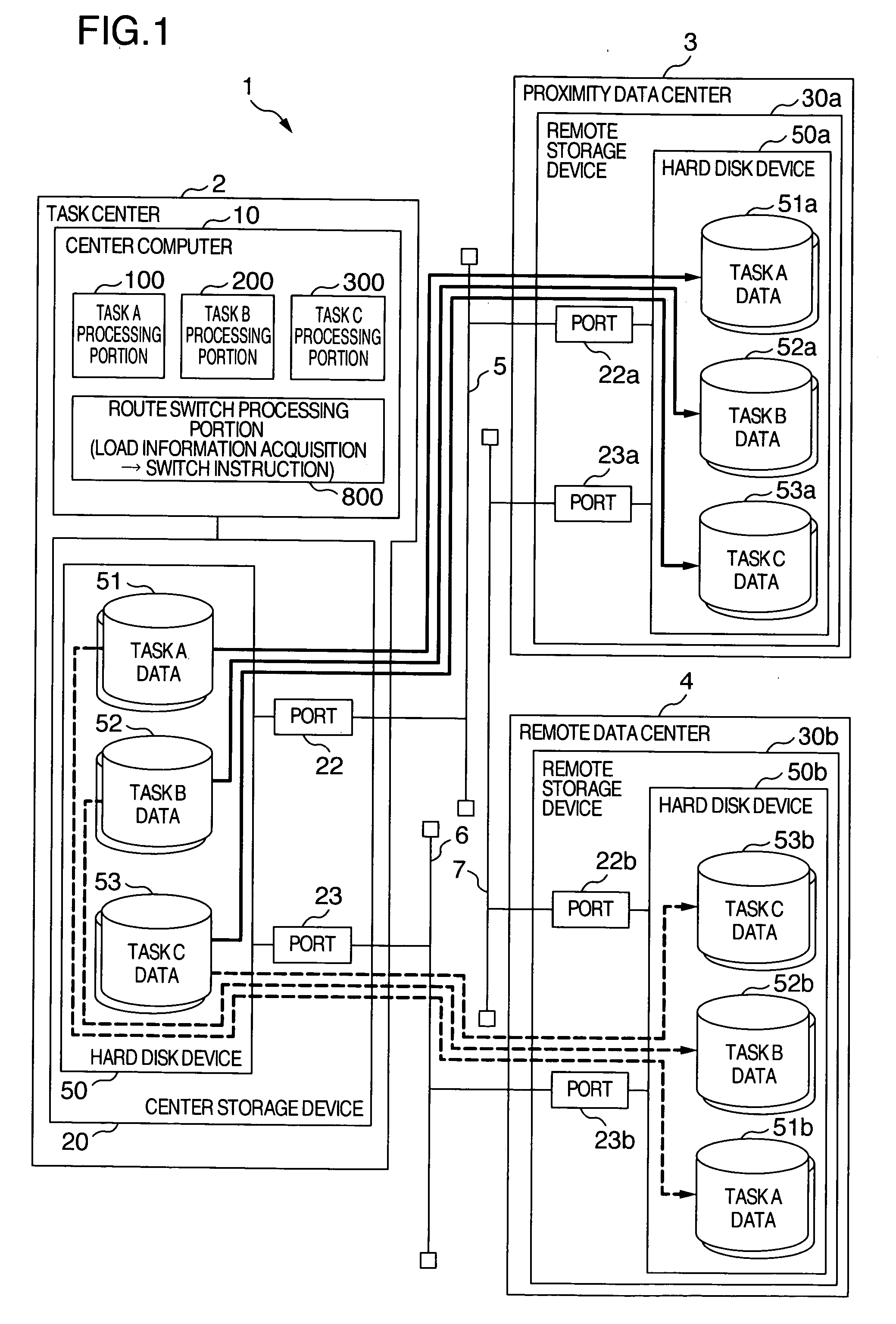
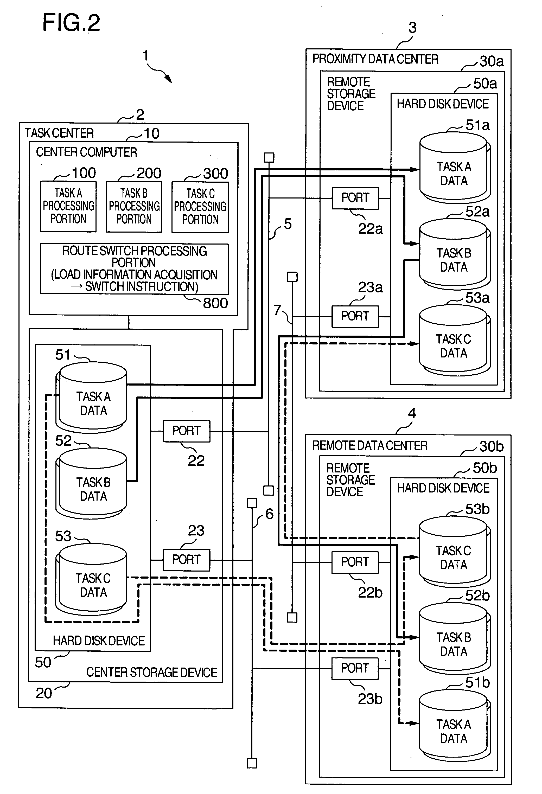
[0026] To begin with, a schematic construction of a remote copy storage device system according to an embodiment of the invention and a method for preventing an overload of a communication line will be explained with reference to FIGS. 1 and 2. FIG. 1 shows a schematic construction of a remote copy storage device system according to an embodiment and an example of a transmission route of copy data under a normal condition.

[0027] The remote copy storage device system 1 includes a task center 2 in which a center computer 10 and a center storage device 20 are installed, a proximity data center 3 in which remote storage device 30a is installed and a remote data center 4 in which a remote storage device 30b is installed. The center storage device 20 and the remote storage device 30a of the proximity data center 3 are connected to each other throu...


PUM


Abstract

Overload of communication lines and the drop of through-put of task processing in a center computer is prevented. The center computer executes a plurality of task processing, writes the execution result to a center storage device and remote copies the same data to a plurality of remote storage devices. At this time, the center computer acquires loads of communication lines through load measurement portions and stops the execution of a part of the task processing involved with the transmission of the copy data through the communication line when its load exceeds a predetermined threshold value. When the center storage device and the remote storage devices switch the transmission route of the copy data to other route, the center computer starts again the execution of the task processing previously stopped and starts again the remote copy.

Description

INCORPORATION BY REFERENCE [0001] The present application claims priority from Japanese application JP2005-338333 filed on Nov. 24, 2005, the content of which is hereby incorporated by reference into this application. BACKGROUND OF THE INVENTION [0002] This invention relates to a remote copy storage device system, a center computer and a remote copy method each of which is used for storing the same information as information stored in a center storage device to a plurality of remote storage devices. [0003] Computers and their networks have now become indispensable infrastructures to support economical activities of human being. When any fault occurs in the computer as the infrastructure, therefore, great influences are exerted not only on the economic activities of companies but also on the social lives of ordinary people. Among the faults of the computers, the loss of data stored in storage devices is the most serious and critical of all. Hardware and software constituting the comp...

Claims


Application Information

Patent Timeline
IPC IPC(8): G06F9/46G06F3/06G06F12/00G06F13/00H04L12/701
CPCG06F3/0613G06F3/0635G06F3/065G06F3/067G06F9/5083H04L67/1008H04L67/1002H04L67/1012H04L67/1001
Inventor AMAKI, KENSUKEWATANABE, KAZUHIKO
Owner HITACHI LTD
Why Eureka
Try Eureka