
Cornice Corner Cap and Methods Related Thereto

a technology for corner caps and trim parts, applied in the field of siding products, can solve the problems of increasing labor and expertise for siding installation as corner structures of buildings, increasing the cost of wooden products, and increasing the cost of wood products, so as to reduce the intrusion of water or insects

Inactive Publication Date: 2007-05-31
CERTAINTEED CORP
View PDF19 Cites 35 Cited by
  • Summary
  • Abstract
  • Description
  • Claims
  • Application Information

AI Technical Summary

Benefits of technology

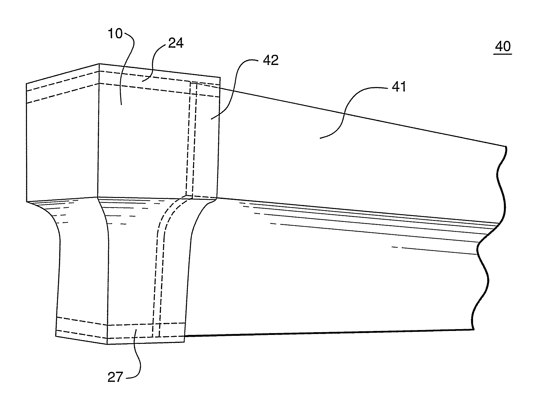
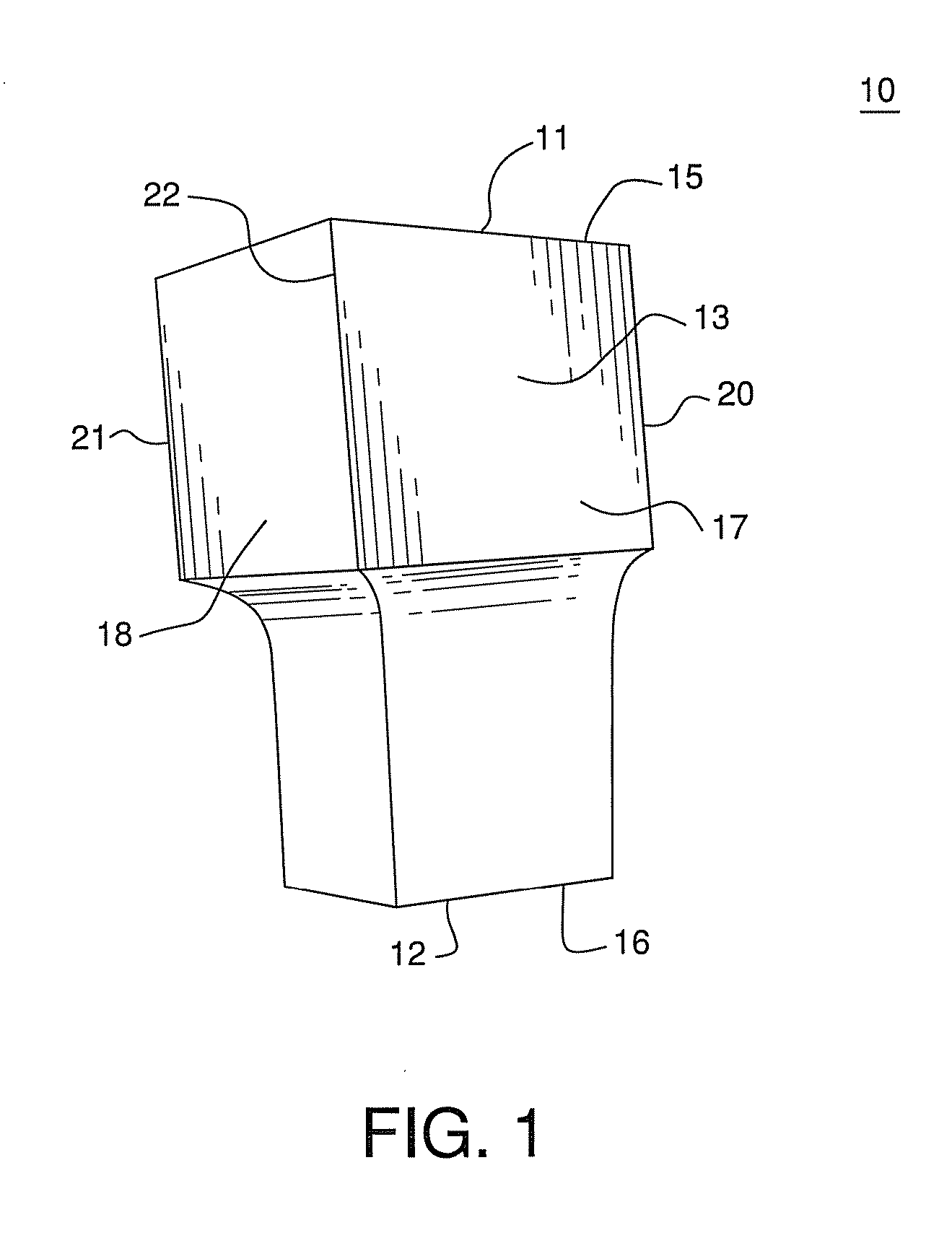
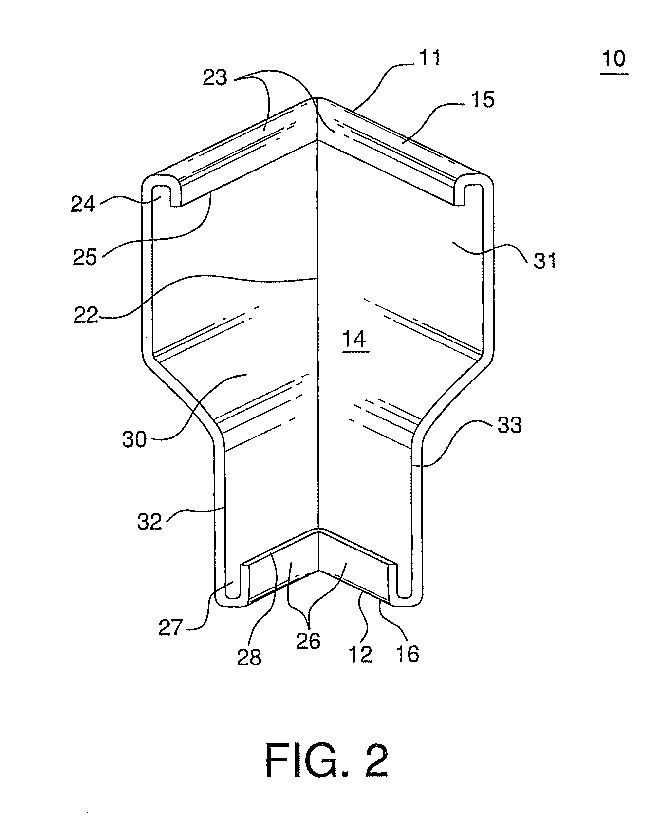
[0015] In certain embodiments, the present invention also provides a system and an assembly for the finishing of a corner of a siding installation having an uppermost course of siding on each of two adjacent walls that meet at a corner structure, a siding corner piece installed at the corner structure, and first and second cornice molding strips installed on each of the walls above the top edges of the uppermost courses of siding panels under an eave or soffit structure, with the ends of the cornice molding strips having a gap between them adjacent the corner. The system and the assembly further include a preformed cornice molding corner cap installed over the ends of each of the two cornice molding strips at the corner structure, thereby concealing the gaps between the ends of the cornice molding strips and covering the corner. The cornice molding corner cap accommodates thermal expansion of the cornice molding strip and is resistant to displacement. The corner cap also acts to create a barrier at the joint of the cornice molding trim to minimize intrusion of water or insects into the building structure at the top of the wall corner.
[0016] The preformed cornice molding corner cap, method, system and assembly enable easy finishing of corners of siding installations employing shake shingle impression siding, as well as, other siding installations employing finished corner pieces without the use of a corner post having a receiver pocket for siding panel ends. The preformed cornice molding corner cap is useful for trim applications on buildings clad with polymeric siding such as vinyl or polypropylene, fiber cement siding, or other types of siding, cladding or sheathing where a finished mitered corner trim appearance is desired.

Problems solved by technology

While the installation of exterior siding panels is relatively straightforward, installing siding as corner structures of the building requires more labor and expertise.
Unfortunately, these wooden products require constant maintenance, and are extremely expensive, as well as labor intensive to install.
However, for more decorative corners simulating shake impressions, such as, for example, U.S. Pat. No. 4,015,391 to Epstein and U.S. Pat. No. 6,684,587 to Shaw, there is no pocket to conceal the end of trim.
However, this process is laborious and time consuming and requires special carpentry skills.
It also would yield a tightly fitted corner joint that could be damaged by distortion caused by thermal expansion and contraction with dimensional changes of a polymeric cornice molding trim accessory.
This approach, while potentially providing space to allow for a rougher end cutting of the cornice trim and allowing for dimensional changes of the strip, suffers from the need for time, labor, and special skills in metal working to produce an aesthetically pleasing corner cap.
Also, an aluminum cap could be susceptible to denting and permanent deformation or other damage or dislodgement by impacts or winds.
These difficulties have led some users to avoid the use of siding products that do not employ corner posts having siding receiver pockets and avoiding the use of exposed polymer based cornice molding strips that require a mitered joint finish at the corner.

Method used


Image

  • Cornice Corner Cap and Methods Related Thereto
  • Cornice Corner Cap and Methods Related Thereto
  • Cornice Corner Cap and Methods Related Thereto

Examples


example i

[0068] In a first trial, a force gauge with a hook was used to pull the cornice molding, in the absence of a cornice molding corner cap, from the receiver until the molding was dislodged from the receiver. The pulling force was directed perpendicularly away from the wall near the end of the molding strip. The force was measured to remove the molding from the receiver channel.

example 2

[0069] In a second trial, a cornice molding corner cap of the present invention was installed over cornice molding accessory strips mounted to the wall using F-channel receiver strips nailed to the wall. A pushing force was imposed against the cornice molding corner cap at a lateral edge of the cap adjacent to one of the molding strips in a direction parallel to a first molding strip toward the end of the molding strip covered by the cap. The force was applied to the cap until either the cap was dislodged or the second molding strip, perpendicular to the direction of the applied force, was forced out of the receiver strip. A force transducer was used to measure the imposed force through the course of the test. FIGS. 16 and 16b depict the test in progress with assembly 500, FIG. 16b being slightly later during the test than FIG. 16. A first cornice molding strip 501 was mounted on the wall by receiver strip 504. Second cornice molding strip 502 was mounted on the adjacent wall around...

example 3

[0070] In a third trial, a cornice molding corner cap of the present invention was installed over cornice molding accessory strips mounted to the wall using F-channel receiver strips nailed to the wall. A pulling force was imposed on the cornice molding corner cap using a force gauge with a hook fixture attached to the end of the force probe. The fixture was hooked over the top of the cap at the corner to engage a force on the cap. The force was imposed along an angle bisecting the legs of the corner and directly away from the wall. That is to say, the force was directed at an angle of 135 degrees from each of the two walls and in the same plane as the mounting of the two molding strips on the surface of the wall. The force was applied to the cap until either the cap was dislodged or at least one of the molding strips was forced out of its respective receiver strip. FIGS. 17 and 17b depict the test in progress with assembly 600, FIG. 17b being slightly later during the test than FIG...


PUM


Abstract

A cornice molding cap is provided as an accessory to cover or eliminate gaps created where cornice molding meets at a corner of a building. The cap covers gaps where cornice molding meets at a corner structure formed by two walls. The cap is particularly useful in exterior siding installations at corners not employing corner posts having receiver pockets for cladding material end edges. A method of finishing a corner molding installation is described, as is a system for finishing such installation, and an assembly including a unitary cornice molding corner cap.

Description

CROSS REFERENCE TO RELATED APPLICATION [0001] This application claims the benefit of provisional application No. 60 / 734,034, Filed Nov. 4, 2005.FIELD OF THE INVENTION [0002] The present invention relates to siding products generally, and more particularly relates to trim components for finishing corners of siding installations at an uppermost course adjacent to a soffit. BACKGROUND [0003] Various types of siding panels have long been used to clad the exteriors of buildings. Polymer based sidings, such as vinyl or polypropylene, have become very popular exterior finishing products primarily due to its relatively low cost and durability when compared to traditional materials such as wood or metal. Fiber cement siding products have also become very popular. In addition, polymeric and fiber cement siding products can also be provided in a wide variety of colors and patterns. Polymeric siding has an advantage in that it is more flexible and forgiving, and hence, will not deform plastical...

Claims


Application Information

Patent Timeline
Patent Type & Authority Applications(United States)
IPC IPC(8): E04B2/00
CPCE04D13/15E04F19/02
Inventor SHAW, ROBERT D.WERNER, ROBERT W.
Owner CERTAINTEED CORP
Learn More