Three track valve for cryogenic refrigerator

a cryogenic refrigerator and three-track technology, applied in the direction of sealing face pressure relieving devices, transportation and packaging, etc., can solve the problems of requiring an increased amount of torque, difficult to get to low temperatures, and early pulse tube refrigerators that were not efficient enough to compete with gm type refrigerators, etc., to reduce reduce the diameter of the valve and the torque required to turn it

Inactive Publication Date: 2007-05-31
SUMITOMO HEAVY IND LTD +1
View PDF16 Cites 10 Cited by
  • Summary
  • Abstract
  • Description
  • Claims
  • Application Information

AI Technical Summary

Benefits of technology

[0010] This invention reduces the torque required to turn a rotary face valve that is designed for a multi-valve, preferably four-valve, two-stage pulse tube. This is implemented by designing the valve to have two cooling cycles per revolution and to have the two high-pressure ports to the pulse tubes on a single track, and the two low-pressure ports from the pulse tubes on a separate single track. Flow to the regenerator is through two ports while flow to and from the pulse tubes is through one port each in the valve seat. The two high-pressure ports are approximately 180° apart, as are the low pressure ports, and the ports to the 2nd stage pulse tube are slotted to increase the open period and advance the opening relative to the 1st stage ports. The slots in the valve disc are symmetrical, and have a width that provides the desired open time for the 1st stage ports.
[0011] Relative to a valve that has one cooling cycle per revolution it reduces the number of tracks from five to three, one being for flow to and from the regenerator, the others for flow to and from the warm ends of the two pulse tubes. The reduction in the number of tracks also reduces the diameter of the valve and the torque required to turn it.

Problems solved by technology

This type of valve has the disadvantage of requiring an increased amount of torque as the diameter is increased to accommodate larger ports or ports for multiple valves.
Early pulse tube refrigerators were not efficient enough to compete with GM type refrigerators.
The high speed makes it difficult to get to low temperatures so GM type pulse tubes running at low speed are typically used for applications below about 20K.
This increases the diameter of the valve and consequently significantly increases the torque.

Method used


Image

  • Three track valve for cryogenic refrigerator
  • Three track valve for cryogenic refrigerator
  • Three track valve for cryogenic refrigerator

Examples


Embodiment Construction

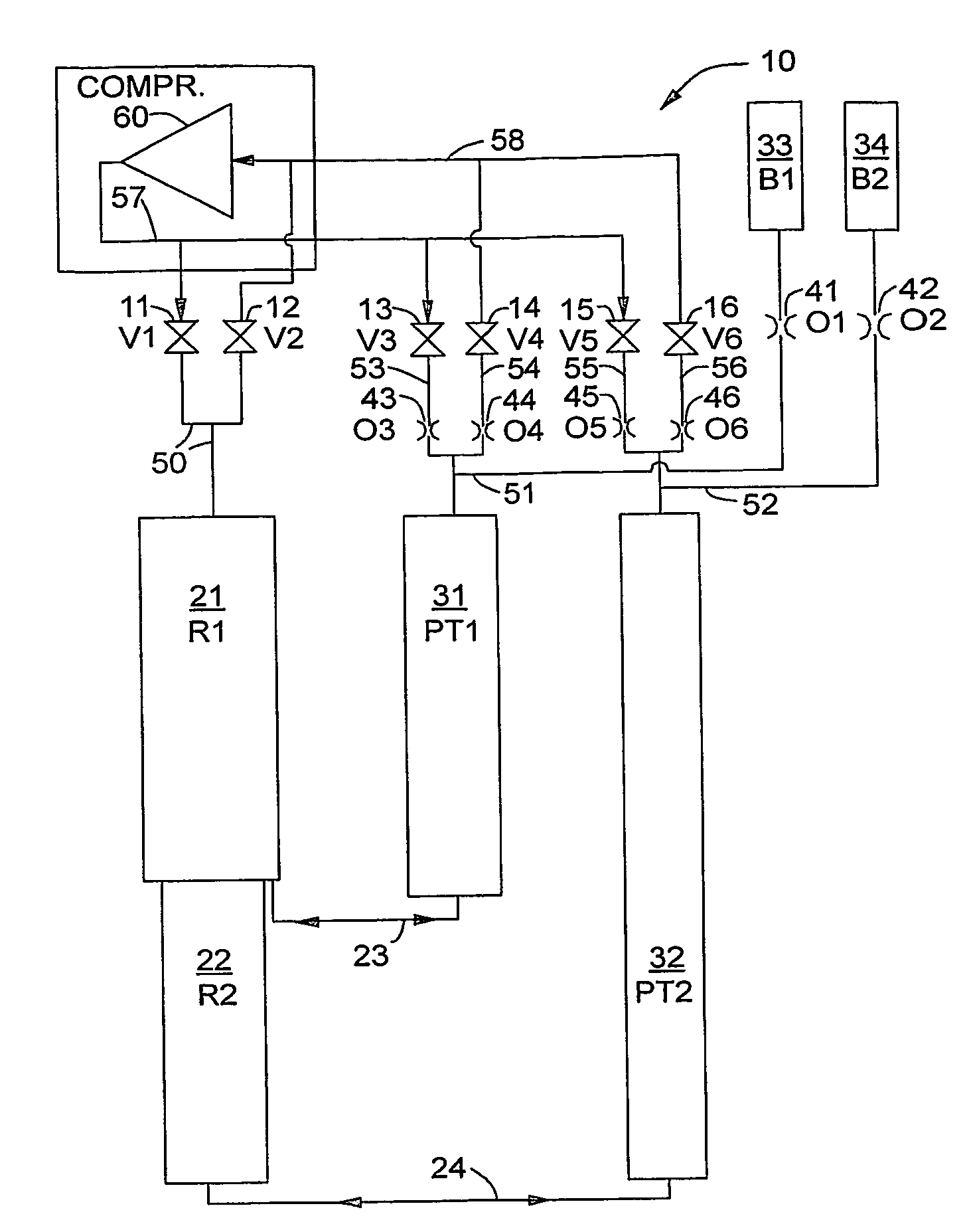
[0019] The present invention is applicable to a four-valve GM type two-stage pulse tube refrigerator.

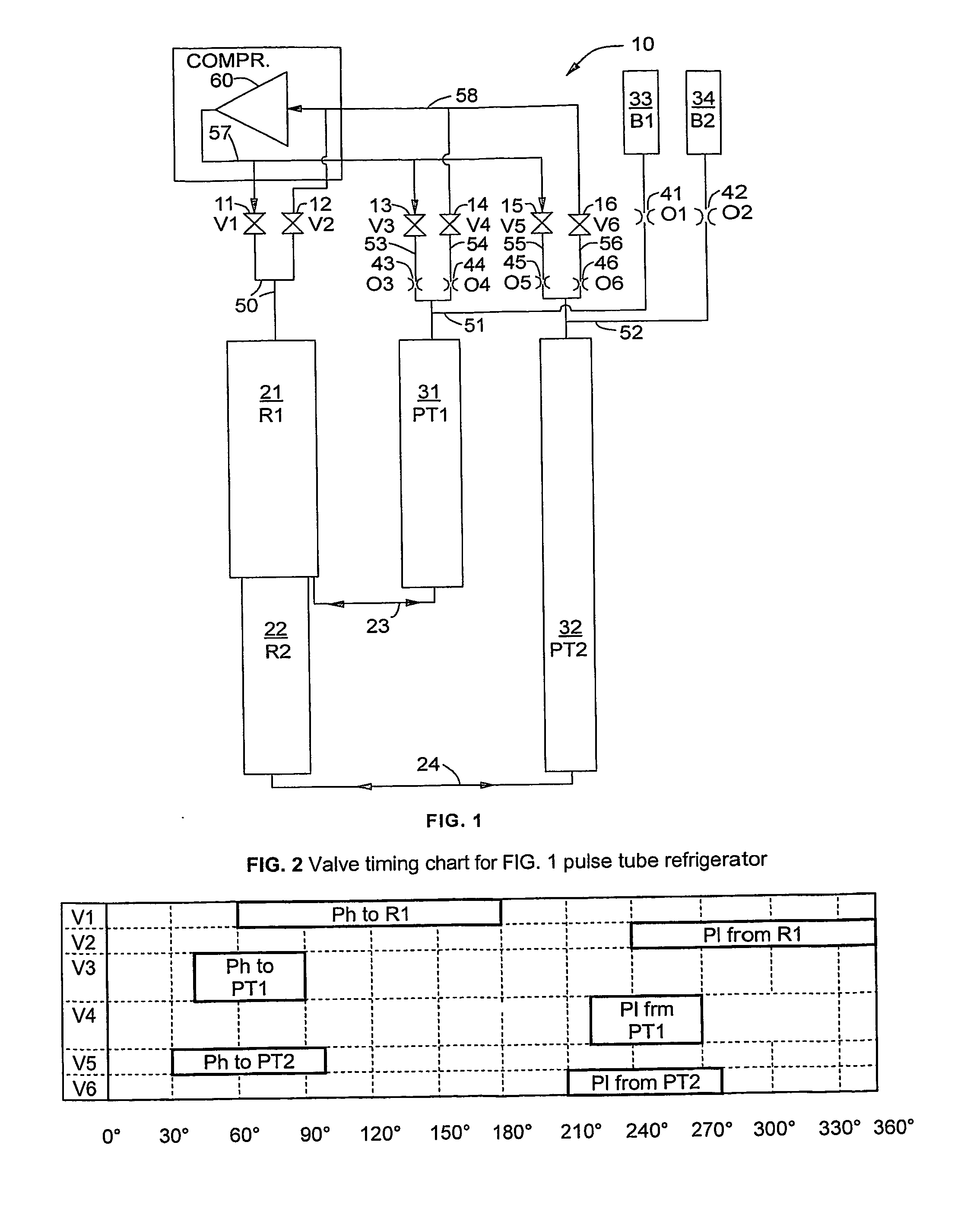
[0020]FIG. 1 is a schematic of a two-stage four-valve pulse tube refrigerator 10 that shows the gas flow paths through the system. FIG. 1 shows some refinements in the basic two-stage four-valve pulse tube refrigerator that is illustrated in FIG. 9 of U.S. Pat. No. 6,256,998. High-pressure gas, Ph, flows from compressor 60 through gas line 57 to valves 11 (V1), 13 (V3), and 15 (V5). Low-pressure gas, P1, returns to compressor 60 from valves 12 (V2), 14 (V4), and 16 (V6) through line 58. Valves V1 and V2 control the flow to and from regenerator 21 (R1) through line 50. Valve V3 controls the flow to the first stage pulse tube 31 (PT1) through line 53, orifice 43 (O3) and line 51. Valve V53 controls the flow to the second stage pulse tube 32 (PT2) through line 55, orifice 45 (O5) and line 52. Valve V4 controls the flow from PT1 through line 51, orifice 44 (O4) and line 54. Valve V6 con...


PUM


Abstract

A multi valve two-stage pulse tube type GM refrigerator having a rotary valve that comprises one track for flow to the regenerator and two tracks for flow to the pulse tubes where the valve has two high pressure ports to the pulse tubes located on a single track and two low pressure ports from the pulse tubes located on a separate single track and where there are two cooling cycles per revolution of the rotary face valve.

Description

[0001] This application claims the benefit of U.S. Provisional Application No. 60 / ,544144filed Feb. 11, 2004.BACKGROUND OF THE INVENTION [0002] The present invention relates to Gifford McMahon (GM) type pulse tube refrigerators. Coldheads of such cryogenic refrigerators include a valve mechanism, which commonly consists of a rotary valve disc and a valve seat. There are discrete ports, which, by periodic alignment of the different ports, allow the passage of a working fluid, supplied by a compressor, to and from the regenerators and working volumes of the coldhead. [0003] GM type refrigerators use compressors that supply gas at a nearly constant high pressure and receive gas at a nearly constant low pressure. The gas is supplied to a reciprocating expander that runs at a low speed relative to the compressor by virtue of a valve mechanism that alternately lets gas in and out of the expander. Gifford, U.S. Pat. No. 3,205,668, discloses a multi-ported rotary disc valve that uses the hi...

Claims


Application Information

Patent Timeline
Patent Type & Authority Applications(United States)
IPC IPC(8): F25B9/00F16K5/00F16K39/00F25B9/10F25B9/14
CPCF25B9/10F25B9/145F25B2309/006F25B2309/1408F25B2309/1411F25B2309/1418F25B2309/14181F25B2309/1424Y10T137/86863
Inventor GAO, JIN LIN
Owner SUMITOMO HEAVY IND LTD
Why Eureka
Try Eureka