
Pneutmatic fixing machine

a technology of pneumatic fixing machine and pneumatic actuator, which is applied in the direction of mechanical equipment, non-mechanical valves, valve details, etc., can solve the problems of inconvenient use of the machine, and excessive attention required by the operator for pressing the trigger, etc., and achieves the effect of simple structur

Active Publication Date: 2007-05-31
FASCO
View PDF8 Cites 7 Cited by
  • Summary
  • Abstract
  • Description
  • Claims
  • Application Information

AI Technical Summary

Benefits of technology

[0012] An object of the present invention is to propose a pneumatic fixing machine to operate in both single or automatic repeated high frequency hit modality, that is compact and having a relatively simple structure, with a small number of components, therefore economic to realize and to assemble.
[0013] Other object is to propose a machine having sure and reliable operation, simple to be used also by a unskilled operator, reducing the risk of an unintentional actuating of the automatic modality at minimum.
[0014] Further object is to propose a fixing machine that allows the operator a firm and sure, correct and comfortable handling from the ergonomic point of view.

Problems solved by technology

A disadvantage of such type of operation consists in the excessive sensibility and attention required to the operator for pressing the trigger, in order to avoid to unintentionally and unawares operate the automatic operation rather than the single hit.
In this case, the disadvantage resides in the discomfort of employment of the machine, because the operator is forced, to get the single hit, to press the trigger with the index and contemporarily the button with the thumb of the same hand, by realizing a non optimal handling and, therefore, inadequate firm and sure of the utensil.
A drawback of such known machines consists in their structural and constructive complexity, that comprises numerous parts and components, resulting therefore expensive to build and to assemble.

Method used


Image

  • Pneutmatic fixing machine
  • Pneutmatic fixing machine
  • Pneutmatic fixing machine

Examples


Embodiment Construction

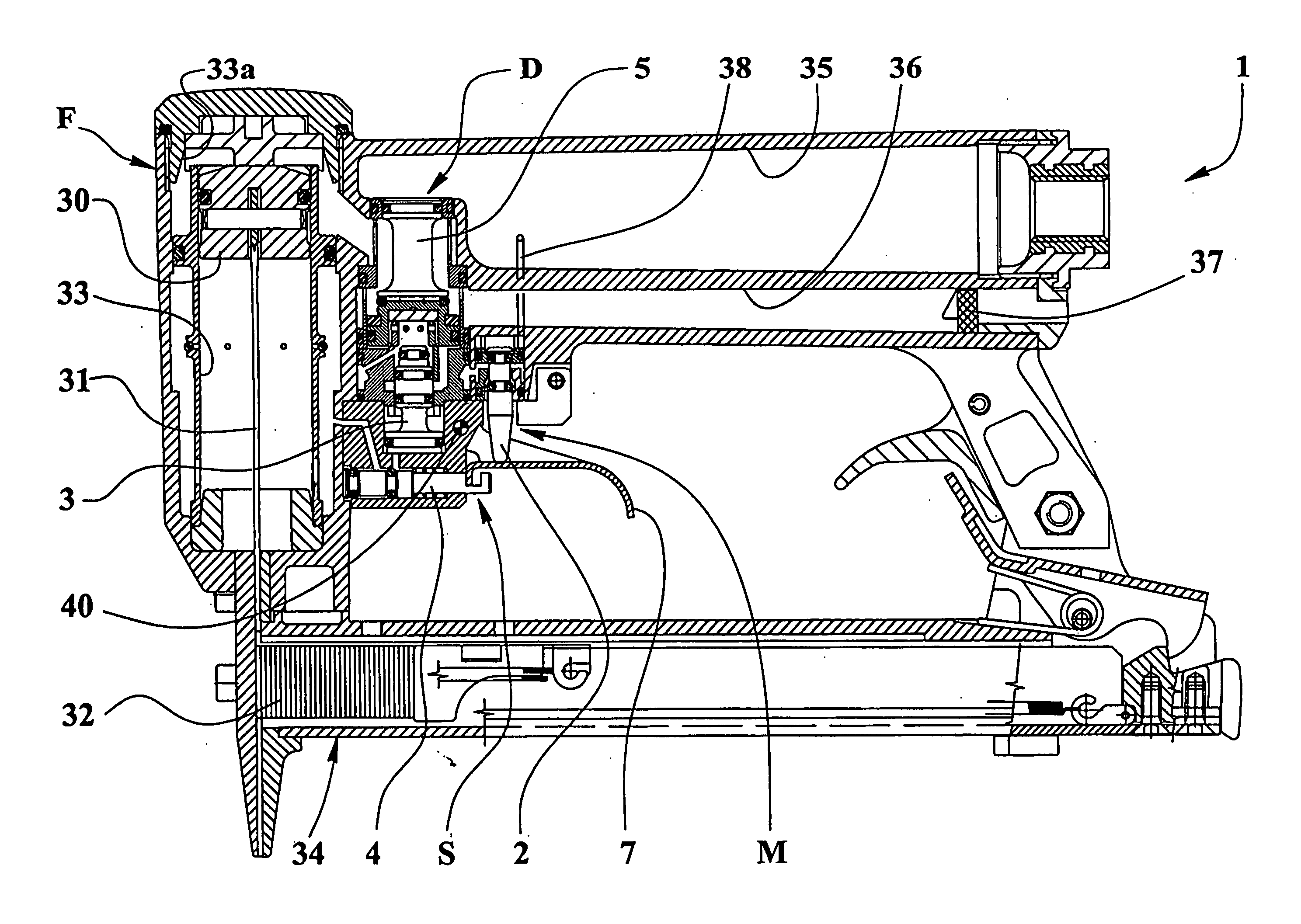
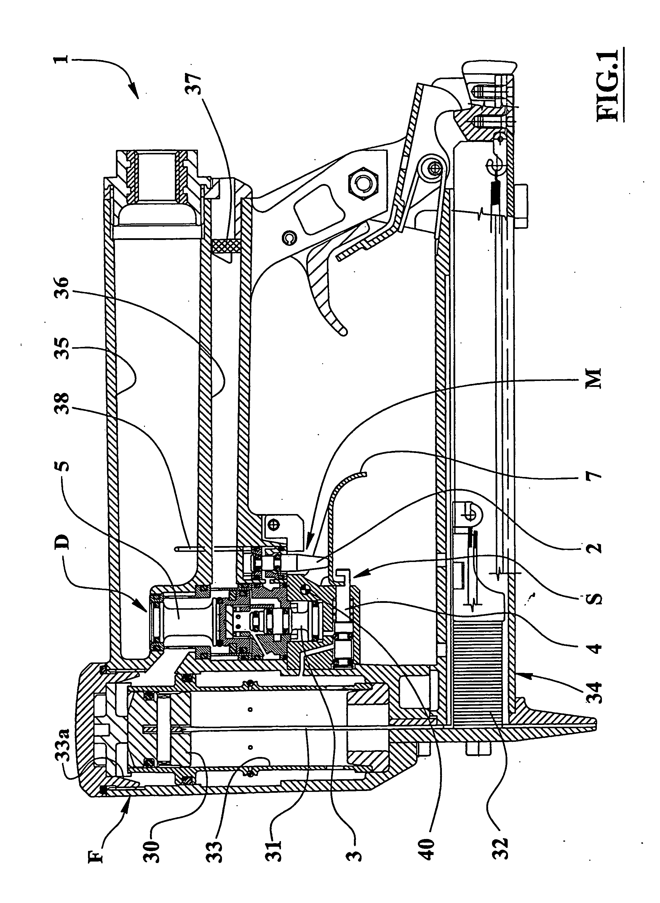
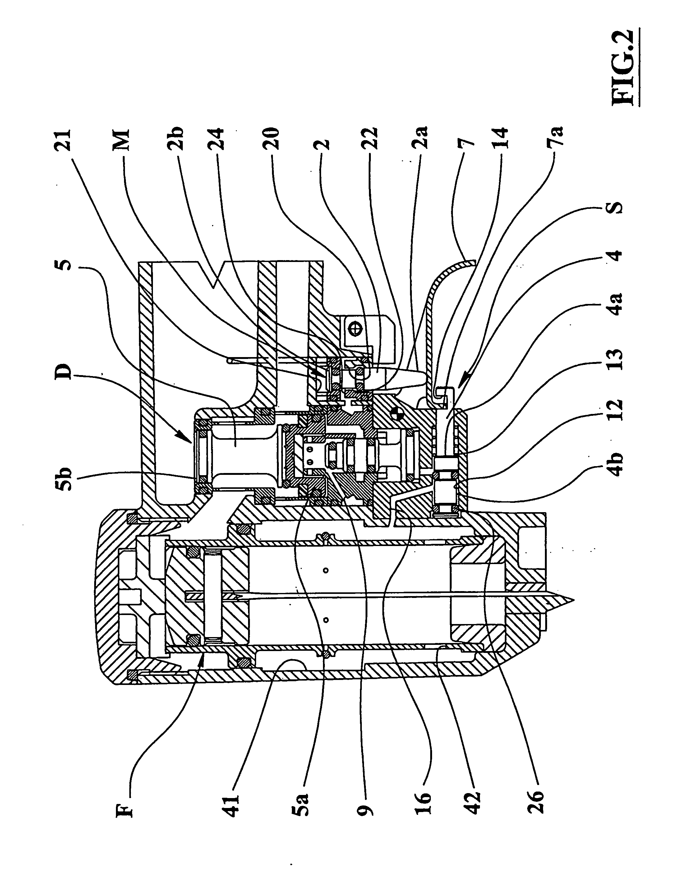
[0021] With reference to the figures from 1 to 6, with 1 is designed the pneumatic fixing machine, object of the present invention, of the type comprising a piston mean 30, sliding inside a cylinder 33 and supporting a beating blade 31, fit to act on a fixing 20 mean 32, for instance a metallic staple or a pin, contained in a magazine 34 of known type and associated to the machine 1. The piston is actuated and controlled in its motion through first valve means 5, second 2, third 3 and fourth 4 located inside the machine 1.

[0022] The first valve means 5 are mobile between two extreme opening E and closing D 25 positions, in correspondence of which they connect in flow communication an inlet portion 33a of said cylinder 33 respectively with a feeding of pressurized fluid and with an external outlet.

[0023] More precisely, the inlet portion 33a can selectively be connected in communication 30 with a feeding room 35 containing pressurized air and connected to an external source of comp...


PUM

PropertyMeasurementUnit
pressureaaaaaaaaaa
elastic strengthaaaaaaaaaa
cylindrical shapeaaaaaaaaaa

Abstract

A pneumatic fixing machine comprises a piston mean (30) sliding into a cylinder (33); first valve means (5) mobile between two extreme opening (E) and closing (D) positions, in correspondence of which they connect in flow communication a inlet portion (33a) of said cylinder (33) respectively with a feeding of pressurized fluid and with an external outlet; second valve means (2) which can be operated by means of a trigger mean (7) and mobile at least between an occlusion position (M) and a passage position (L) to connect in flow connection, through at least a first duct (9), a base portion (5a) of the first valve means (5) respectively with the feeding of fluid in pressure and with an external outlet. The machine (1) comprises:—third valve means (3) mobile between a position of obstruction (N) and a crossing position (Q), respectively to cut off or to open a flow connection between the duct (9) and the first valve means (5);—fourth valve means (4) which can be operated by means of the trigger mean (7) and mobile between a block position (S) and a transit position (T), in which respectively they obstruct or make free a flow connection between the cylinder (33) and the third valve means (3).

Description

TECHNICAL FIELD [0001] The present invention relates to the technical field of the portable pneumatic fixing machines, such as riveting machines, staplers, and particularly it refers to a pneumatic fixing machine provided for a manual use and able to operate in single hit or in automatic modality with repeated hits. BACKGROUND ART [0002] There are known machines as staplers e / o riveting compressed air machines provided with valves and control and regulation means allowing the single hit or automatic repetition operation or the release of a single fixing mean, for instance a metallic staple, a pin, a nail, etc., or the release of a plurality of such fixing means in sequence, with different timing. [0003] The actuating of the two different modalities is generally obtained by partially or completely, up the stop, pressing the trigger of the utensil or pressing two separate triggers or pushers. [0004] Such trigger or pusher, in fact, subsequently crushes two separate command pivots plac...

Claims


Application Information

Patent Timeline
Patent Type & Authority Applications(United States)
IPC IPC(8): B25C1/04
CPCB25C1/043B25C1/042
Inventor RONCONI, MARCO
Owner FASCO
Features
  • Generate Ideas
  • Intellectual Property
  • Life Sciences
  • Materials
  • Tech Scout
  • Unparalleled Data Quality
  • Higher Quality Content
  • 60% Fewer Hallucinations
Learn More