
Display mounting device

a technology for mounting devices and displays, applied in washstands, lighting support devices, electrical apparatus casings/cabinets/drawers, etc., can solve the problems of difficult individual task, tedious removal of threaded fasteners to move the display, and prior art mounting devices that are not entirely suitable for such applications, etc., to achieve quick and easy mounting, convenient repositioning, lock and disengage

Active Publication Date: 2007-05-31
LEGRAND AV INC
View PDF27 Cites 17 Cited by
  • Summary
  • Abstract
  • Description
  • Claims
  • Application Information

AI Technical Summary

Benefits of technology

[0009] The mounting apparatus of the present invention substantially meets the aforementioned needs of the industry. The present invention includes a flat panel display mounting apparatus that enables quick and easy mounting and dismounting of the flat panel display. As a result, the flat panel display is readily repositionable to alternative locations. The mounting apparatus of the present invention is self aligning and easily engaged, locked, and disengaged. Further, the mounting apparatus of the present invention provides firm structural mounting of the display to reduce the risk of injury to persons and damage to the display during seismic events, severe weather, or other such occurrences. Further, the invention may include a securing and locking mechanism to reduce the likelihood of theft of the flat panel display.

Problems solved by technology

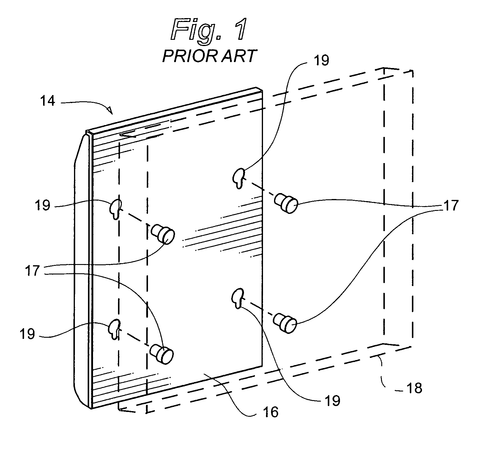
Prior art mounting devices, however, have not been entirely suitable for such applications requiring frequent moving of the display.
While such devices offer the desirable quality of rigid support for the display, removal of the threaded fasteners to move the display is tedious, time consuming and sometimes awkward due to the need to support the display as the fasteners are removed.
This may be a difficult task for an individual where the display is heavy, bulky, or is being handled overhead from a ladder or manlift.
Further, when the display is lifted upward during dismounting, the fastening button may snag on the top or sides of the keyhole slot, inhibiting removal of the display.
Moreover, flat panel displays remain relatively expensive devices.

Method used


Image

  • Display mounting device
  • Display mounting device
  • Display mounting device

Examples


Embodiment Construction

[0037] The present invention relates to a mounting system for attaching an electronic display to a fixed structure, and particularly a system adapted for and / or intended to be used with a flat panel electronic display. A flat panel display includes a plasma display, a liquid crystal display, or any present or future kind of display that is similarly relatively flat or having a relatively minimal depth dimension. A fixed structure includes any portion of a building, such as a wall, ceiling, beam, or column, or other similar permanent or temporary structure, portable support structures such as trade show booths, and any other object or structure, such as a pole, to which a display device may be attached.

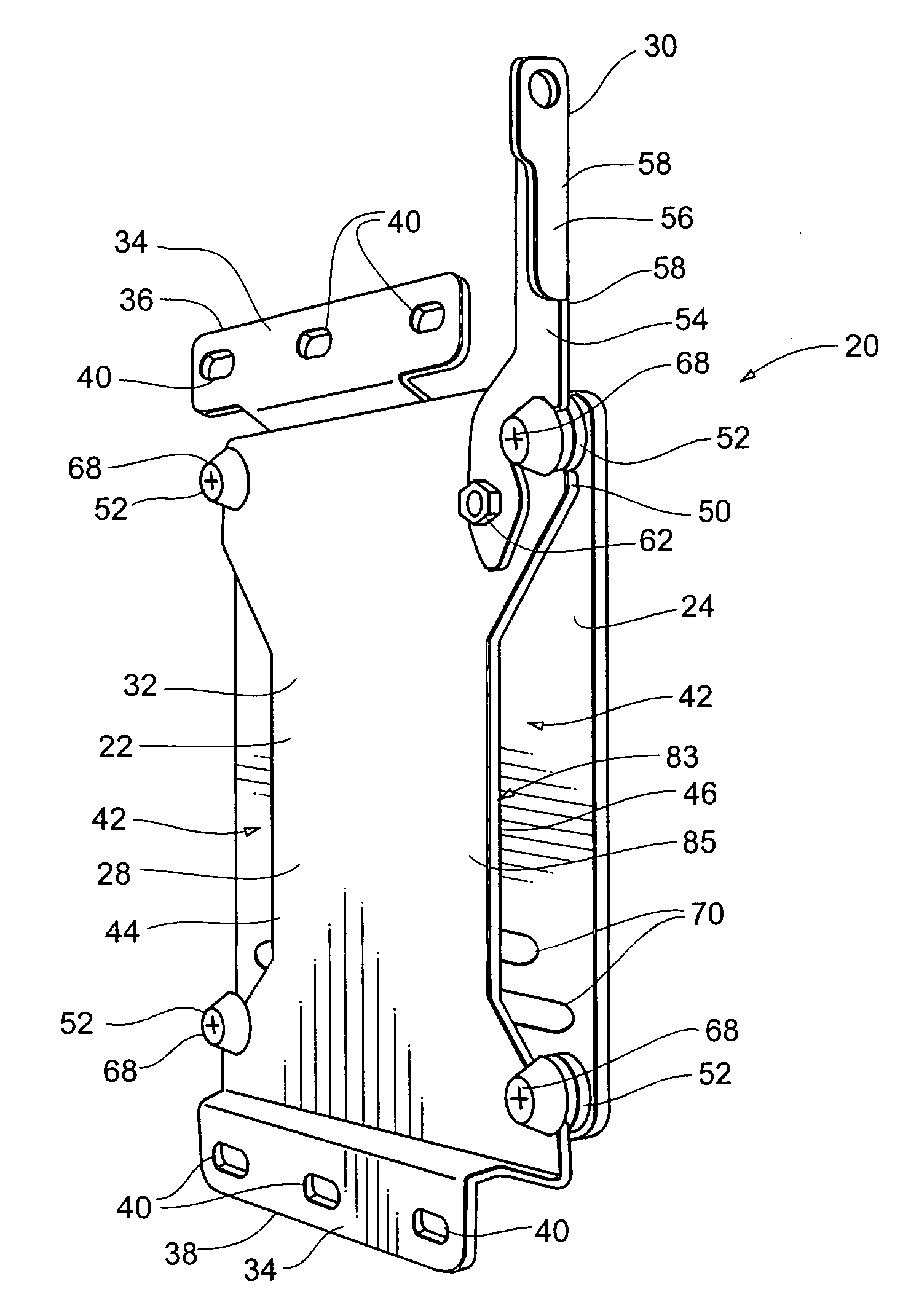
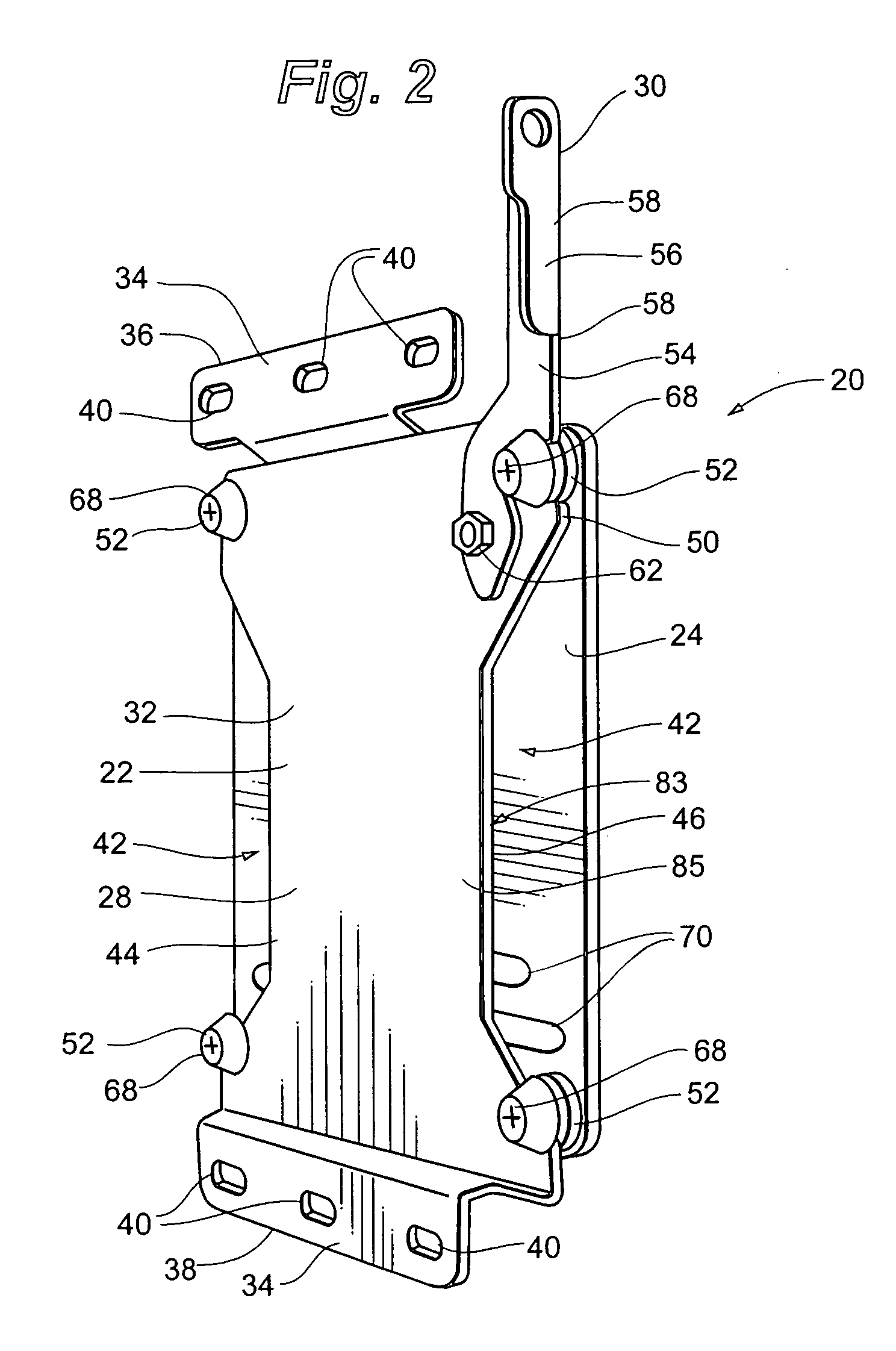
[0038] A first embodiment of a flat panel display mounting device 20 is depicted in FIGS. 2 and 10. Mounting device 20 generally includes mount bracket 22 and device interface bracket 24. According to the invention, a flat panel display device 26 may be fastened to device interface br...


PUM


Abstract

A flat panel display mounting apparatus that enables quick and easy mounting and dismounting of the flat panel display. The system includes a first bracket having a periphery defining a plurality of spaced apart notches and a second bracket selectively removably receivable on the first bracket that includes a plurality of fastening buttons, each fastening button defining a slot. The fastening buttons are spaced apart and positioned correspondingly with the notches of the first bracket so that the slot of each fastening button receives the periphery of the first bracket at a separate one of the notches when the second bracket is received on the first bracket.

Description

RELATED APPLICATIONS [0001] This application is a divisional of U.S. patent application Ser. No. 10 / 889,464, filed Jul. 12, 2004, entitled DISPLAY MOUNTING DEVICE, which claims priority to U.S. Provisional Patent Application No. 60 / 486,503, filed Jul. 11, 2003, entitled DISPLAY MOUNTING DEVICE, both of which are hereby fully incorporated by reference.FIELD OF THE INVENTION [0002] The invention relates generally to video display-mounting devices. More particularly, the present invention relates to mounts for flat panel displays. BACKGROUND OF THE INVENTION [0003] Flat panel electronic displays, such as LCD and plasma monitors, are now widely used in commercial settings to display information due to their higher resolution and compact size relative to conventional CRT displays. In commercial locations where large numbers of people may need to view the display and where space may be at a premium, it is generally desirable to mount the display overhead. Accordingly, devices of many diff...

Claims


Application Information

Patent Timeline
Patent Type & Authority Applications(United States)
IPC IPC(8): A47B96/00A47K1/00F16M11/04F16M11/10F16M13/02
CPCF16M11/04F16M11/041F16M11/10F16M13/02Y10S248/917F16M2200/028Y10T292/0917
Inventor DITTMER, JAY
Owner LEGRAND AV INC
Learn More