Uncooled infrared sensor

Inactive Publication Date: 2007-05-31
BAE SYST INFORMATION & ELECTRONICS SYST INTERGRATION INC
View PDF27 Cites 75 Cited by
  • Summary
  • Abstract
  • Description
  • Claims
  • Application Information

AI Technical Summary

Problems solved by technology

In contrast, uncooled infrared detectors do not make use of the small band gap semiconductor device beca

Method used


Image

  • Uncooled infrared sensor
  • Uncooled infrared sensor
  • Uncooled infrared sensor

Examples


Embodiment Construction

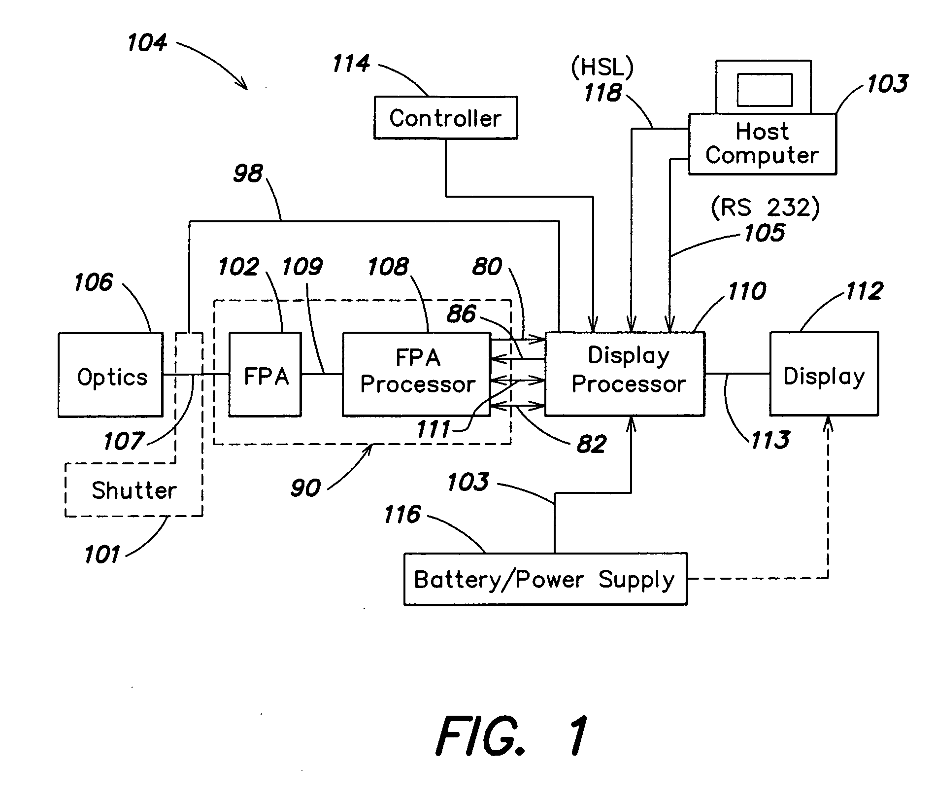
[0062]FIG. 1 illustrates a schematic block diagram of an embodiment of an uncooled infrared sensor according to the present invention. With the imaging system of FIG. 1, electromagnetic radiation such as, for example, infrared radiation in a wavelength range of 8-14 μm may be incident upon optics 106, focussed by the optics such as, for example, a lens to provide a focussed electromagnetic signal at output 107. The focussed electromagnetic signal is imaged onto an uncooled focal plane array (FPA) 102. The FPA converts the focussed electromagnetic signal to a plurality of sensed signals that are output on medium 109, to a focal plane array processor 108. The focal plane array processor 108 processes the plurality of sensed signals such as, for example, by digitizing the plurality of sensed signals to provide a plurality of digital signals and by adjusting the plurality of digital signals for any differences in gain or other non-uniformities between the plurality of detector devices o...


PUM


Abstract

An uncooled infrared sensor can be used for a plurality of applications such as fire fighting, surveilling a border or any desired area, and limb sounding. The uncooled infrared sensor includes manually or automatically adjustable optics that receive an electromagnetic signal, focus the electromagnetic signal and provide a focused electromagnetic signal to a focal plane array. The focal plane array includes a plurality of detector devices disposed in rows and columns to form the focal plane array. Each detector device is constructed so as to have a reduced pitch and provide a maximum number of detectors within a minimum square area of the focal plane array. Each detector device detects the focused electromagnetic signal incident upon it, converts the focused electromagnetic signal into a sensed signal and outputs the sensed signal so that the focal plane array provides a plurality of sensed signals. The sensor also includes a focal plane array processor that has a plurality of cells corresponding to the plurality of detector devices. The focal plane array processor receives the plurality of sensed signals, processes the plurality of sensed signals to correct for any gain and any offset errors between the plurality of sensed signals due to any inconsistencies between any of the detector devices of the focal plane array and any inconsistencies within the cells of the focal plane array processor itself, and outputs a plurality of processed signals. The sensor also includes a display processor that receives the plurality of processed signals and converts the plurality of processed signals into a video signal suitable for display. The focal plane array processor, the display processor and a controller also provide temperature stabilization of the sensor, manual or automatic calibration of the sensor, manual or automatic gain and level control of the sensor and automatic or manual calibration of the sensor.

Description

CROSS REFERENCES TO RELATED APPLICATIONS [0001] This application claims the benefit under 35 U.S.C. §120 as a continuation of co-pending U.S. non-provisional application Ser. No. 11 / 211,149, filed Aug. 24, 2005, which is a continuation of co-pending U.S. non-provisional application Ser. No. 11 / 010,826, filed Dec. 13, 2004, which is a continuation of co-pending U.S. non-provisional application Ser. No. 10 / 787,836, filed Feb. 25, 2004, which is a continuation of Ser. No. 10 / 444,500, filed May 23, 2003, which is a continuation of Ser. No. 10 / 254,444, filed Sep. 25, 2002, entitled UNCOOLED INFRARED SENSOR, which is a continuation of Ser. No. 10 / 036,098, filed Nov. 9, 2001, entitled UNCOOLED INFRARED SENSOR, which is a continuation of Ser. No. 09 / 797,424, filed Mar. 1, 2001, entitled UNCOOLED INFRARED SENSOR, which is a continuation of Ser. No. 09 / 584,939, filed Jun. 1, 2000, entitled UNCOOLED INFRARED SENSOR, which is a continuation of Ser. No. 09 / 434,893, filed Nov. 5, 1999, entitled U...

Claims


Application Information

Patent Timeline
IPC IPC(8): G01J5/00
CPCG01J5/061G01J5/10G01J5/20H01L27/14603H01L27/14649H04N5/23293H04N5/33
Inventor BLACKWELL, RICHARDBUTLER, NEAL R.MROCZKOWSKI, JACEK
Owner BAE SYST INFORMATION & ELECTRONICS SYST INTERGRATION INC
Why Eureka
Try Eureka