Power and ground shield mesh to remove both capacitive and inductive signal coupling effects of routing in integrated circuit device
a technology of capacitive and inductive signal coupling and integrated circuit device, which is applied in the field of circuitry, can solve the problems of signal lines becoming even more susceptible to capacitive and inductive coupling and noise from other neighboring signal lines
- Summary
- Abstract
- Description
- Claims
- Application Information
AI Technical Summary
Benefits of technology
Problems solved by technology
Method used
Image
Examples
embodiment 400
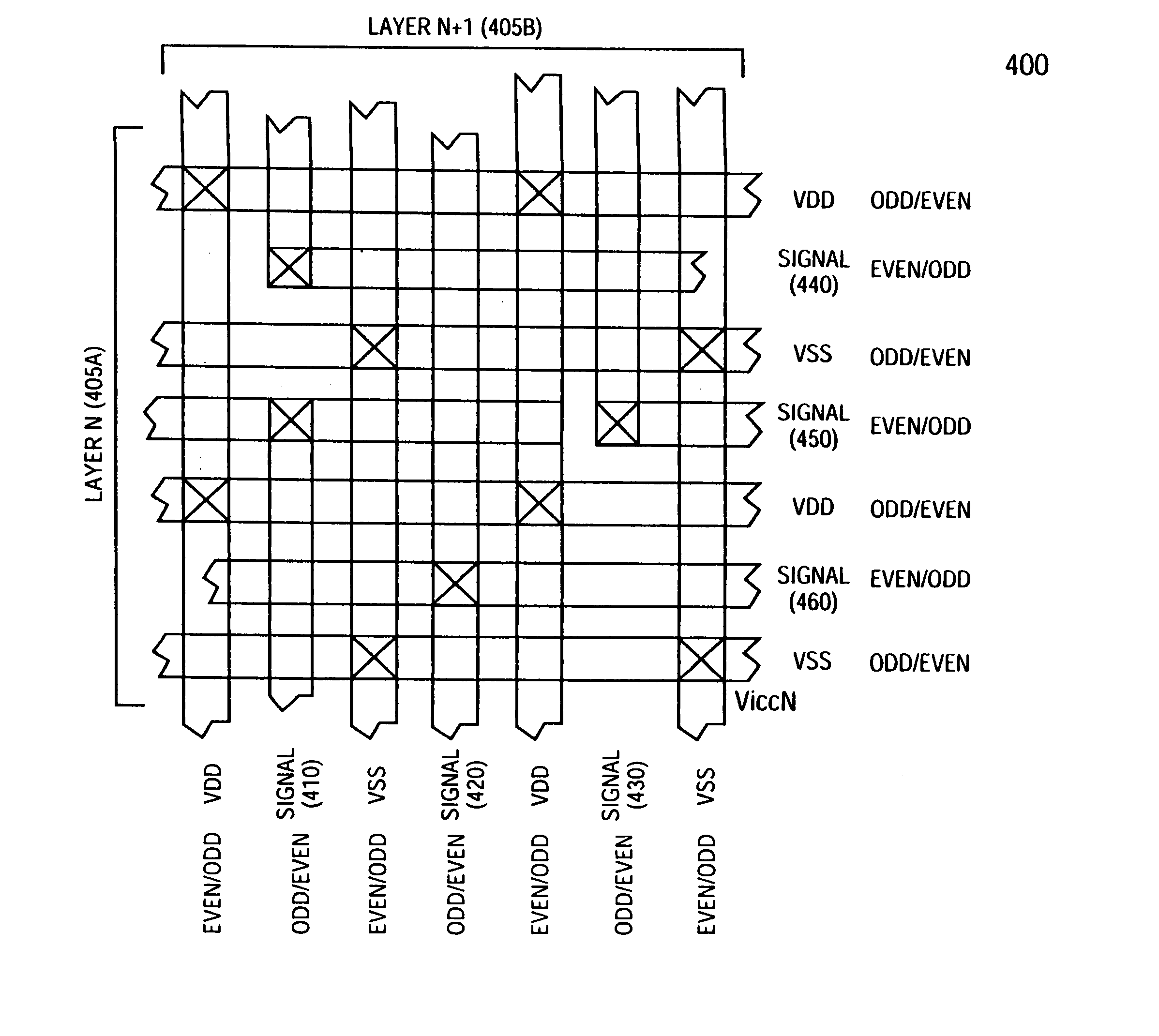
[0032]FIG. 4 is a top view of shield mesh embodiment 400 showing two adjacent substrate layers, 405A and 405B, depicting the signal lines (410, 420 and 430), alternating VDD and VSS lines on each layer and the appropriate vias between the two layers utilizing a grid layout. Each via provides layer connections and also reduces the segment size of the shielding mesh and thereby reduces the effective R-C resistance according to one embodiment of the present invention. It is important to note that on layer N, 405A, if the signal lines 410, 420 and 430 are on odd grid tracks, then the VDD and VSS lines will be on even grid tracks, and vice-versa. Like wise, on layer N+1, 405B, if the signal lines 440, 450 and 460 are on even tracks, then the VDD and VSS lines will alternately be on odd grid tracks and vice-versa.
[0033] Multi-layer routing assignment to signals and shields: for the vertical space, the track assignment should be done so that there would not be signal tracks directly on top...
embodiment 900
[0038]FIG. 9 depicts embodiment 900, which depicts a shielding mesh in the routing channel (910) between blocks on a substrate and also within a block (920) of a substrate. As described in FIG. 8, due to relative small segment lengths of the shielding mesh, the shielding mesh further reduces the effective RC component of the routing line thereby reducing the noise and coupling effects caused by cross-talk between signal lines.
[0039]FIG. 10 illustrates the flow chart of steps for the process, 1000, of an EDA tool in which the shielding mesh of the present invention may be introduced. As shown in this embodiment of the present invention, initial code is generally written using HDL, step 1010, (for example) after which logic synthesis, step 1020, is performed. Placement of a power grid is next performed as shown in block 1030. For example where substrate grid is is utilized, shielding mesh as outlined in one embodiment of the present invention can be introduced as shown at point 1040. ...
PUM
 Abstract
Description
Claims
Application Information
 - R&D
- Intellectual Property
- Life Sciences
- Materials
- Tech Scout
- Unparalleled Data Quality
- Higher Quality Content
- 60% Fewer Hallucinations
Browse by: Latest US Patents, China's latest patents, Technical Efficacy Thesaurus, Application Domain, Technology Topic, Popular Technical Reports.
© 2025 PatSnap. All rights reserved.Legal|Privacy policy|Modern Slavery Act Transparency Statement|Sitemap|About US| Contact US: help@patsnap.com


