Compensator device for stabilising the power of alternators in electrical power generating plants

Inactive Publication Date: 2007-05-31
ANSALDO ENERGIA SPA
View PDF5 Cites 13 Cited by
  • Summary
  • Abstract
  • Description
  • Claims
  • Application Information

AI Technical Summary

Problems solved by technology

One limitation of these conventional compensator devices is that their correct operation requires an accurate knowledge of the physical-mathematical model of the process to be controlled, and that their optimisation is centred only on a narrow working area of the alternator.
Since an accurate knowledge of the process parameters is v

Method used


Image

  • Compensator device for stabilising the power of alternators in electrical power generating plants
  • Compensator device for stabilising the power of alternators in electrical power generating plants
  • Compensator device for stabilising the power of alternators in electrical power generating plants

Examples


first embodiment

[0097] According to this first embodiment, a second order deriving filter is used.

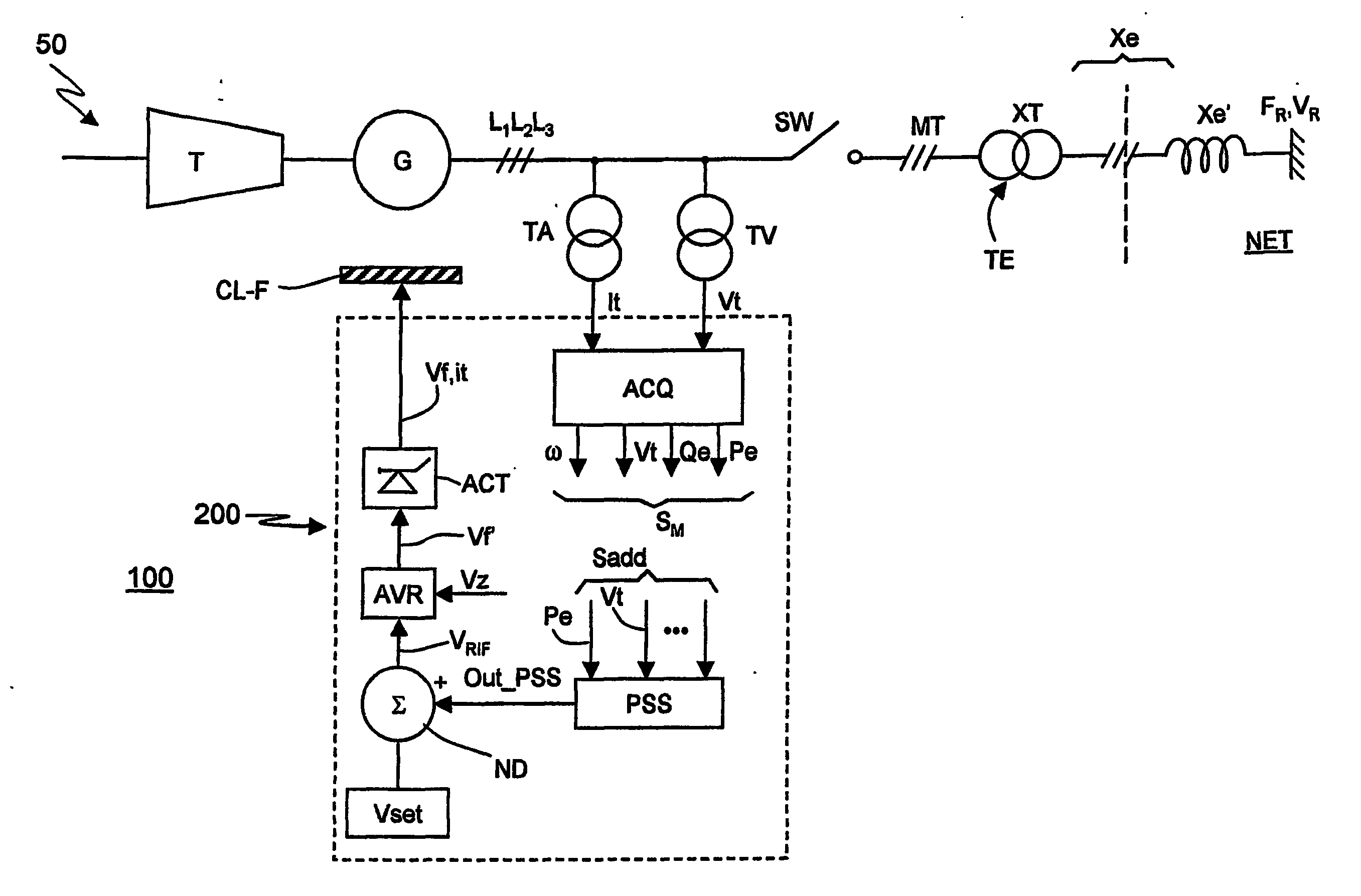
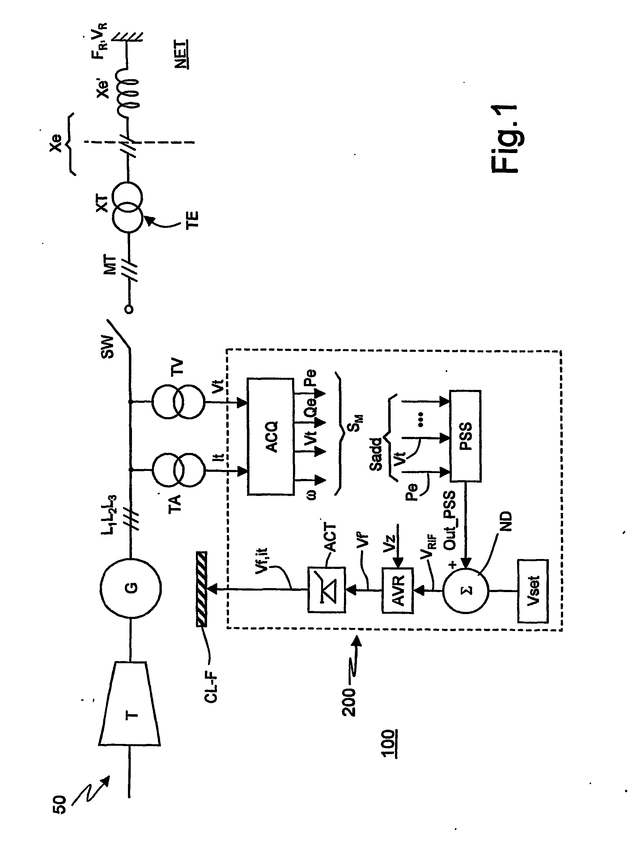
[0098] The stabiliser device PSS is provided with a first 1 and a second 2 input terminal for its main input signal which, according to said example, are active electrical power PE and machine voltage vt.

[0099] The stabiliser device PSS implements the following equations: σ^⁡(t)=(ⅆⅆt+λ)·ξ^.⁡(t)⁢⁢Out_PSS=H·sign⁡(ξ)·f⁡(σ^)·sign⁡(σ^)Equations⁢ ⁢22

[0100] The equations 22 are similar to the equations 15 and to the first of the equations 7. In particular, the symbol “ˆ” indicates that the corresponding quantities are obtained by estimation. Moreover, it should be recalled that the estimated quantity ξ is expressed in accordance with the equation 12.

[0101] In the second of the equations 22, note that the gain H has the sign of ξ to guarantee the sliding modes condition and f(σ) is any suitable function.

[0102] For example, for the sliding modes approximation the function f(σ) is:

f=1, |σ| / Φ>1; f=|σ|, |σ| / Φ&...

second embodiment

[0126]FIG. 4 shows a PSS compensator in accordance with the present invention. According to the embodiment of FIG. 4, the processing of the measurement signals for estimating the sliding surface σ(t) is performed not with a second order filter but with a linear or non linear observer 4′. Moreover, it should be noted that the observer 4′ can be obtained with a sliding modes technique (sliding observers).

[0127] In the diagram of FIG. 4, the same numerical references of FIG. 3 are used to designate identical or similar components.

[0128] The observer 4′ is connected to the output of the divider block 3 to receive the signal PE / vt and to a third input terminal 2′ to receive at least another signal.

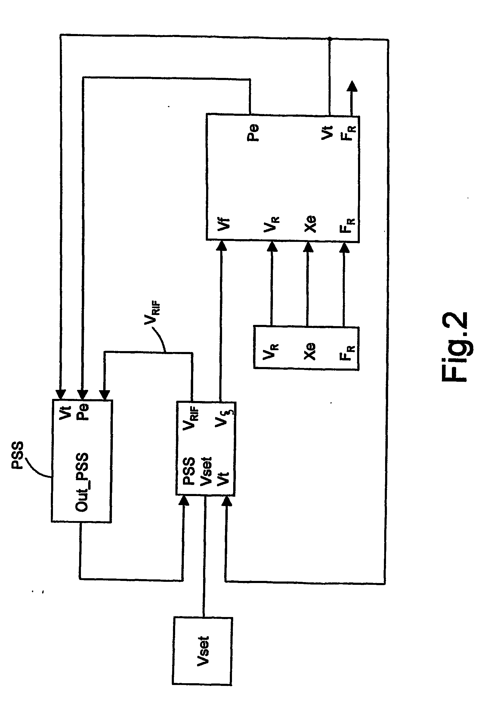
[0129] For example, the third terminal is provided with the voltage reference electrical signal vRIF which is also sent to the voltage regulator AVR shown in FIG. 1. Note that the fact that to the compensator PSS is sent the reference signal of vRIF is also indicated in the diagram of FIG. 2....

third embodiment

[0132]FIG. 5 shows a compensator PSS according to the invention, in which control is based on the measurement of rotor velocity ω. This embodiment is particularly advantageous because the measurement of rotor velocity ω is commonly available in the velocity regulators of turbo-machines and hence can be easily acquired in rapid and precise fashion.

[0133] In this case, one starts from the equations in δ: ⅆδⅆt=ω-ωR=δ.⁡(t)⁢⁢ⅆδ.ⅆt=Cm-CeJ⁢ ⁢con⁢ ⁢Ce=vRxe·(ψq·cos⁢ ⁢δ+ψd·sin⁢ ⁢δ)⁢⁢ⅆ2⁢δ.ⅆt2=C.m-vRxe·[(ψd·cos⁢ ⁢δ-ψq·sin⁢ ⁢δ)·δ.+ⅆψdⅆt·sin⁢ ⁢δ+ⅆψqⅆt·cos⁢ ⁢δ]JEquation⁢ ⁢26

[0134] where, as always, δ is the angle between axis q and the network voltage vector, having amplitude VR, ω is the angular velocity of the reference system integral with axis q (i.e. rotor velocity), ωR is electrical network frequency, and lastly Cm and Ce designate the motive torque and the electrical torque, respectively. Moreover, ψd and ψq are the direct axis flow, and the quadrature axis flow, respectively, and they are...


PUM


Abstract

Compensator device, for the stabilisation of electromechanical oscillations destined to provide a reference signal to a voltage regulator device of a synchronous alternator for the delivery of electrical power to a distribution network, said device including: first processing means to receive electrical measurement signals representing operative parameters characteristics of said synchronous alternator and/or to generate an electrical signal to be controlled; and a first electrical signal corresponding to a sliding surface of a control of the “sliding modes” type, second processing means of the first signal to generate the reference signal so that it has a first order “sliding modes” profile.

Description

TECHNICAL FIELD [0001] The present invention relates to techniques for regulating and controlling the electrical quantities of synchronous machines used in electrical power generating plants. In particular, it pertains to alternator excitation systems and, more explicitly, the automatic control processes with which the new digital voltage regulators and the new stabilising signals (PSS=Power System Stabilisers) contained therein are achieved. BACKGROUND ART [0002] Considering, by way of example, a conventional thermo-electric plant, we observe that each of its generating set comprises a (gas or steam) turbine and a synchronous alternator. [0003] The alternator converts the mechanical energy produced by the turbine into electrical energy to be delivered, in general, on the national electrical supply net. [0004] Both the turbine and the alternator are operated under the control of their respective automatic regulating system: [0005] the speed / load regulator for the turbine, [0006] the...

Claims


Application Information

Patent Timeline
IPC IPC(8): H02J1/00H02J3/00H02J3/01H02J3/18H02K21/00H02K21/48H02P9/30
CPCH02P9/305
Inventor LOMBARDI, FILIPPOMASTRETTA, ROBERTO
Owner ANSALDO ENERGIA SPA
Why Eureka
Try Eureka