
Method and device for geometry analysis and calibration of volumetric imaging systems

a volumetric imaging and geometric analysis technology, applied in the field of volmetric imaging systems, can solve the problems of difficult or impossible to obtain adequate image quality from a scanner, difficult or impossible to directly estimate parameters, and, of course, cannot be applied to volumetric scanners, etc., to achieve the effect of improving accuracy and better images

Active Publication Date: 2007-05-31
GENERAL ELECTRIC CO
View PDF11 Cites 144 Cited by
  • Summary
  • Abstract
  • Description
  • Claims
  • Application Information

AI Technical Summary

Benefits of technology

[0010] It is therefore desirable to provide phantom design and calibration methods for volumetric imagin

Problems solved by technology

Without these critical alignment parameters, it is difficult or impossible to obtain adequate image quality from a scanner, as the image reconstruction process requires an accurate knowledge of scanner geometry to avoid artifacts and blurring in reconstructed images.
Estimating the parameters directly, i.e. for example by making direct measurements on the acquisition system, is often very difficult and the results can be imprecise.
It is, however, not applicable to volumetric scanners, for which a number of additional parameters are required.
However, in other scenarios, e.g., the acquisition of projection data with systems that were originally designed for pure 2D imaging, the system mechanics may be less well defined (e.g., due to mechanical deformability of the gantry), and the synchronization of the image acquisition with the gantry position may also be less accurate.
However, such phantoms and the associated computational approaches work reliably only over a limited range of imaging geometries (tube and detector position and orientation).
In particular, the diameter of the cylinder and pitch of the helical matrix of the phantom limit the utility of such phantoms to a narrow range of magnifications and cone angles.

Method used


Image

  • Method and device for geometry analysis and calibration of volumetric imaging systems
  • Method and device for geometry analysis and calibration of volumetric imaging systems
  • Method and device for geometry analysis and calibration of volumetric imaging systems

Examples


Embodiment Construction

[0025] The present techniques are generally directed to geometrical analysis and calibration of volumetric imaging systems. Such analysis and calibration techniques may be useful in a variety of imaging contexts, such as CT imaging, CT metrology, industrial inspection systems, tomosynthesis, C-arm systems and others. Though the present discussion provides examples in a CT imaging context, one of ordinary skill in the art will readily apprehend that the application of these techniques in other contexts, such as for industrial imaging, and / or tomosynthesis, is well within the scope of the present techniques.

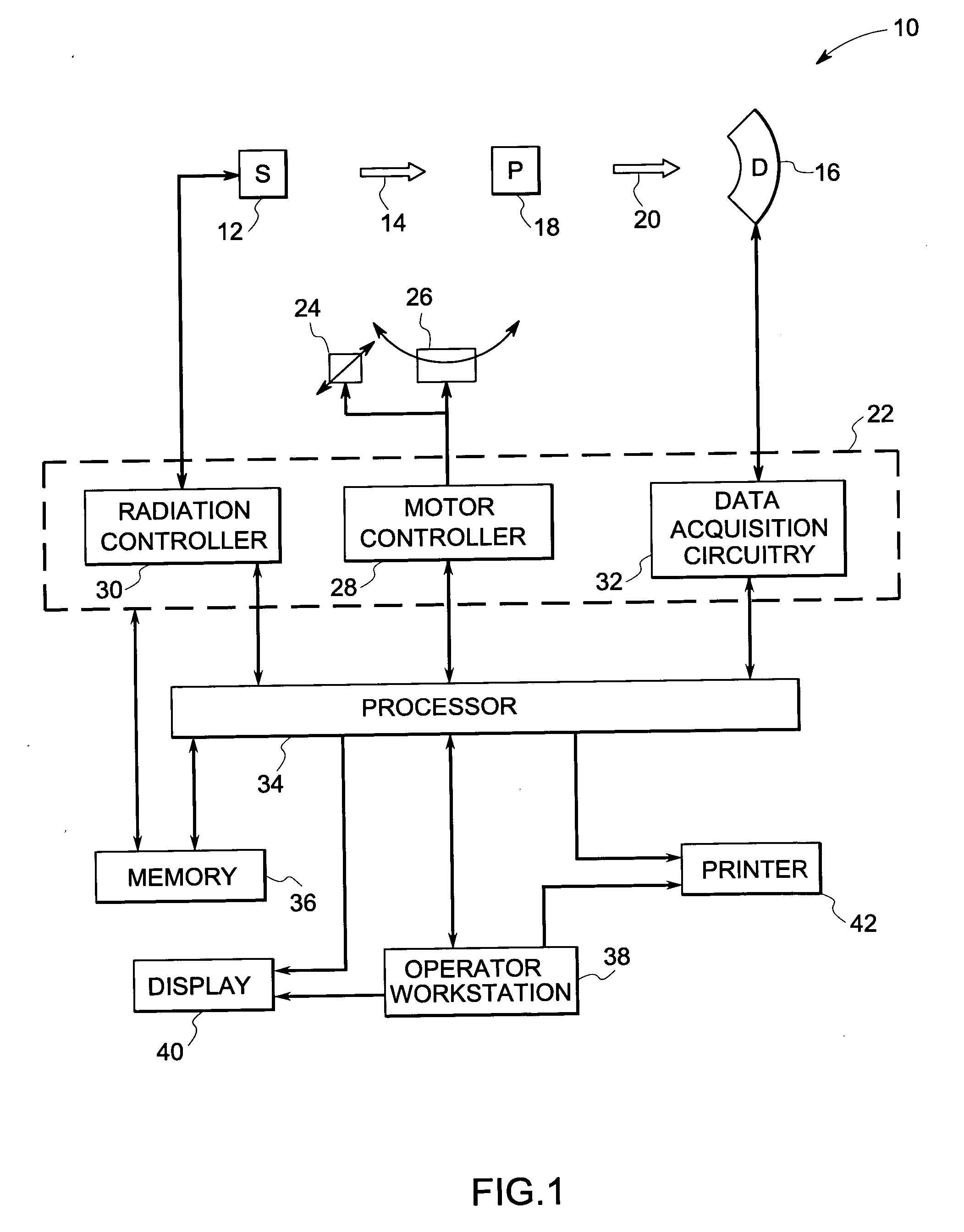
[0026] Referring now to FIG. 1, an imaging system 10 for use in accordance with the present technique is illustrated. In the illustrated embodiment, the imaging system 10 includes a radiation source 12, such as an X-ray source. A collimator may be positioned adjacent to the radiation source 12 for regulating the size and shape of a stream of radiation 14 that emerges from the radi...


PUM


Abstract

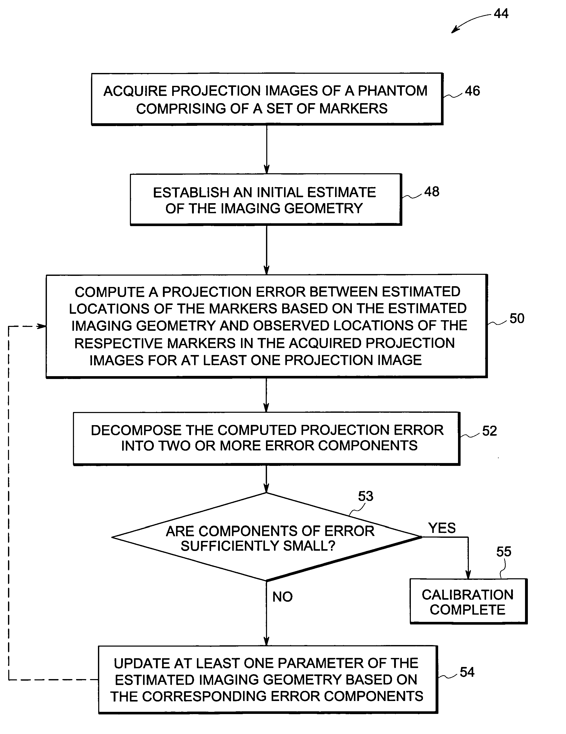
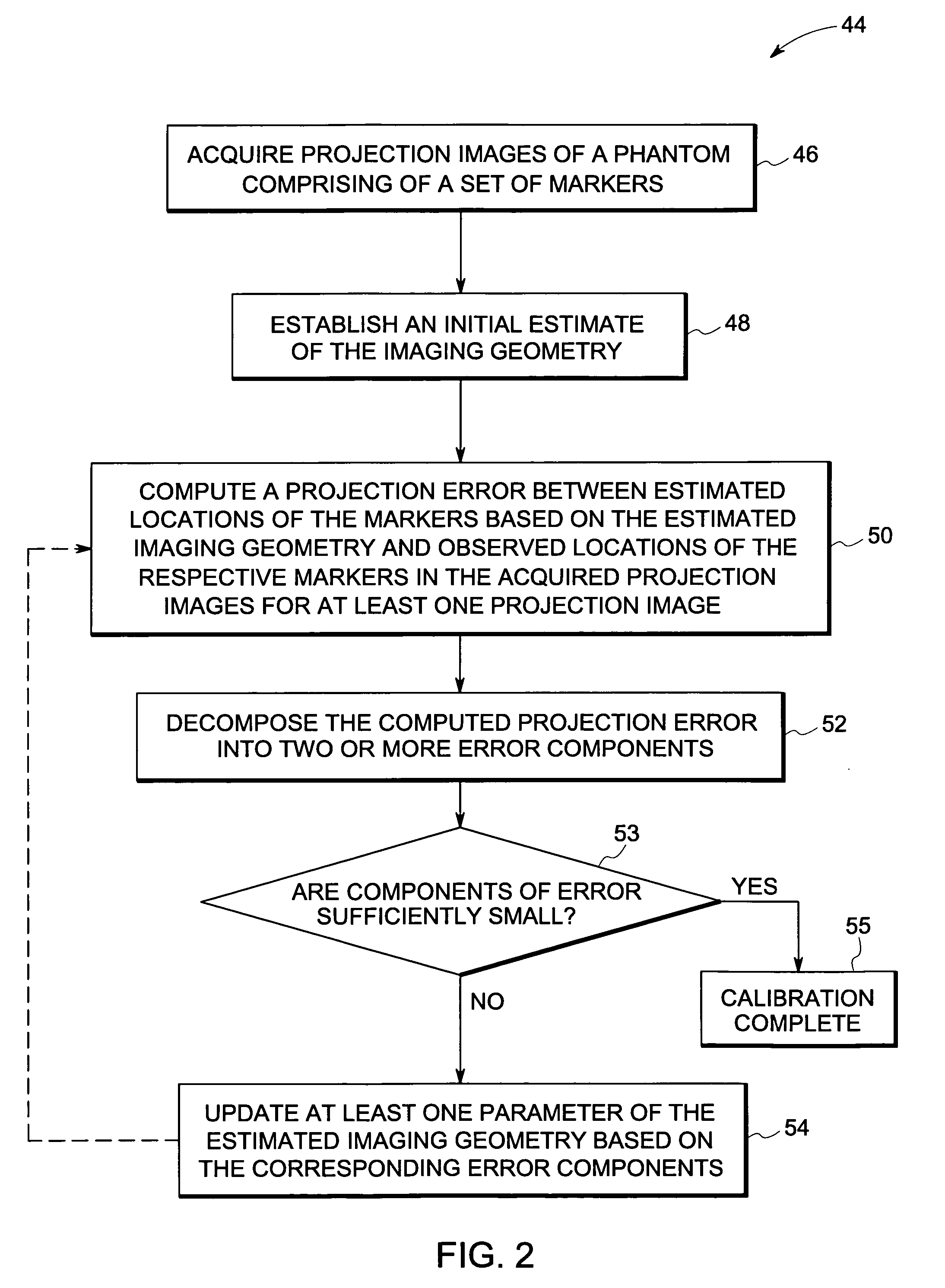
A technique is provided for geometrical analysis and calibration of a volumetric imaging system. The technique includes computing a projection error between estimated locations of a set of markers of a phantom based on a estimated imaging geometry and observed locations of the respective markers for at least one projection image, decomposing the computed projection error into one or more error components corresponding to respective geometric parameters of the imaging geometry, and updating at least one parameter of the estimated imaging geometry based on the one or more error components.

Description

BACKGROUND [0001] The invention relates generally to volumetric imaging systems and more particularly to methods and device for the geometrical analysis and calibration of volumetric imaging systems. [0002] Volumetric imaging systems are utilized for various applications in both medical and non-medical fields. These imaging systems may include for example C-arm, tomosynthesis, computed tomography (CT) imaging systems having varying topologies and are used to create volumetric images or views of a patient based on the attenuation of radiation passing through the patient. Based on the attenuation of the radiation, the topology of the imaging system, and the type and amount of data collected, different views may be constructed, including views showing motion, contrast enhancement, volume reconstructions, two-dimensional images and so forth. Alternatively, volumetric imaging systems may also be utilized in non-medical applications, such as in industrial quality control or in security sc...

Claims


Application Information

Patent Timeline
IPC IPC(8): G06K9/00
CPCA61B6/583G06T11/005
Inventor CLAUS, BERNHARDMANAK, JOSEPH
Owner GENERAL ELECTRIC CO
Learn More